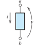
Problem 1.1P: Broadly speaking, what are the two main objectives of electrical systems? Problem 1.2P Problem 1.3P: List eight subdivisions of electrical engineering. Problem 1.4P Problem 1.5P Problem 1.6P: In the fluid-flow analogy for electrical circuits, what is analogous to a conductor; an open switch;... Problem 1.7P: The charge of an electron is 1.601019C . A current of 1 A flows in a wire carried by electrons. How... Problem 1.8P: The ends of a length of wire are labeled a and b. If the current in the wire is iab=5A , are... Problem 1.9P: The circuit element shown in Figure P1.9 has v=12V and iba=2A . What is the value of vba ? Be sure... Problem 1.10P Problem 1.11P: The net charge through a cross section of a circuit element is given by q(t)=2+3tC . Find the... Problem 1.12P: The current through a particular circuit element is given by i(t)=10sin(200t) A in which the angle... Problem 1.13P: The current through a given circuit element is given by i(t)=2etA Find the net charge that passes... Problem 1.14P: The net charge through a cross section of a certain circuit element is given by q(t)=33e2tC... Problem 1.15P: A copper wire has a diameter of 2.05 mm and carries a current of 15 A due solely to electrons.... Problem 1.16P: A certain lead acid storage battery has a mass of 30 kg. Starting from a fully charged state, it can... Problem 1.17P: A circuit element having terminals a and b has vab=10V and iba=2A . Over a period of 20 seconds, how... Problem 1.18P: An electron moves through a voltage of 9 V from the positive polarity to the negative polarity. How... Problem 1.19P: A typical “deep-cycle” battery (used for electric trolling motors for fishing boats) is capable of... Problem 1.20P: Define the term passive reference configuration. When do we have this configuration when using... Problem 1.21P: Compute the power for each element shown in Figure P1.21. For each element, state whether energy is... Problem 1.22P: The terminals of an electrical device are labeled a and b. If vab=10V , how much energy is exchanged... Problem 1.23P: The terminals of a certain battery are labeled a and b. The battery voltage is vab=12V . To increase... Problem 1.24P: The element shown in Figure P1.24 I has v(t)=10V and i(t)=2et A. Compute the power for the circuit... Problem 1.25P: The current and voltage of an electrical device are iab(t)=5A and vab(t)=10sin(200t)V in which the... Problem 1.26P: Suppose that the cost of electrical energy is $0.12 per kilowatt hour and that your electrical bill... Problem 1.27P: Figure P1.27 shows an ammeter (AM) and voltmeter (VM) connected to measure the current and voltage,... Problem 1.28P: Repeat Problem P1.27 with the meters connected as shown in Figure P1.28. Figure P1.28 Problem 1.29P: A certain type of D-cell battery that costs $0.50 is capable of producing 1.2 V and a current of 0.1... Problem 1.30P: The electronics aboard a certain sailboat consume 50 W when operated from a 12.6-V source. If a... Problem 1.31P: What s a node in an electrical circuit? Identify the nodes in the circuit of Figure P1.31. Keep in... Problem 1.32P: State Kirchhoff’s current law. Problem 1.33P: Two electrical elements are connected in series. What can you say about the currents through the... Problem 1.34P: Suppose that in the fluid-flow analogy for an electrical circuit the analog of electrical current is... Problem 1.35P: Identify elements that are in series in the circuit of Figure P1.31. Problem 1.36P: Consider the circuit shown in Figure P1.36. Which elements are in series? What is the relationship... Problem 1.37P: Use KCL to find the values of ia, ic , and id for the circuit of Figure P1.37. Which elements are... Problem 1.38P: Find the values of the other currents in Figure P1.38 if ia=2A , ib=3A , id=5A , and ih=4A Figure... Problem 1.39P Problem 1.40P: State Kirchhoff’s voltage law. Problem 1.41P: Consider the circuit shown in Figure P1.36. Which elements are in parallel? What is the relationship... Problem 1.42P: Use KVL to solve for the voltages va , vb, and vc in Figure P1.42. Figure P1.42 Problem 1.43P: Solve for the other voltages shown in Figure P1.43 given that va=5V , vb=7V, vf=10V , and vf=10V... Problem 1.44P: Use KVL and KCL to solve for the labeled currents and voltages in Figure P1.44. Compute the power... Problem 1.45P: Identify elements that are in parallel in Figure P1.37, in Figure P1.43, in Figure P1.44. Problem 1.46P: Points a, b, c, and d appear in a certain circuit. We know that vob=5V,vcb=15V , and vda=10V .... Problem 1.47P: In your own words, define an ideal conductor; an ideal voltage source; an ideal current source. Problem 1.48P: Name four types of dependent sources and give the units for the gain parameter for each type. Problem 1.49P: State Ohm’s law, including references. Problem 1.50P: Draw a circuit that contains a 5 resistance, a 10-V independent voltage source, and a 2-A... Problem 1.51P: Repeat Problem P1.50, placing all three elements in parallel. Problem 1.52P: The resistance of a certain copper wire is 0.5. . Determine the resistance of a tungsten wire having... Problem 1.53P: Draw a circuit that contains a 5 resistor, a 10-V voltage source, and a voltage-controlled voltage... Problem 1.54P: Draw a circuit that contains a 5 resistor, a 10-V voltage source, and a current-controlled voltage... Problem 1.55P: A power of 100 W is delivered to a certain resistor when the applied voltage is 100 V. Find the... Problem 1.56P: The voltage across a 10 resistor is given by v(t)=5e2tV . Determine the energy delivered to the... Problem 1.57P: The voltage across a 10 resistor is given by v(t)=5sin(2t)V . Determine the energy delivered to the... Problem 1.58P: A certain wire has a resistance of 0.5 . Find the new resistance if the length of the wire is... Problem 1.59P: Plot i versus v to scale for each of the parts of Figure P1.59. Figure P1.59 Problem 1.60P: Which of the following are self-contradictory combinations of circuit element? A 12-V voltage source... Problem 1.61P: Consider the circuit shown in Figure P1.61. Find the power for the voltage source and for the... Problem 1.62P: Consider the circuit shown in Figure P1.62. Find the current iR flowing through the resistor. Find... Problem 1.63P: Consider the circuit shown in Figure P1.63. Find the current iR flowing through the resistor. Find... Problem 1.64P: Consider the circuit shown in Figure P1.64. Use Ohm’s law, KVL, and KCL to find Vz . Figure P1.64 Problem 1.65P: Determine the value of Ix in the circuit shown in Figure P1.65. Figure P1.65 Problem 1.66P: Consider the circuit shown in Figure P1.66. Figure P1.66 Which elements are in series? Which... Problem 1.67P Problem 1.68P: Consider the circuit shown in Figure P1.68. Figure P1.68 Which elements are in sense? Which elements... Problem 1.69P: Solve for the currents shown in Figure P1.69. Figure P1.69 Problem 1.70P: The circuit shown in Figure P1.70 contains a voltage-controlled voltage source. Figure P1.70 Use KVL... Problem 1.71P: Determine the value of vx and iy in the circuit shown in Figure P1.71. Figure P1.71 Problem 1.72P: A 10-V independent voltage source is in series with a 2-A independent current source. What single... Problem 1.73P: A 10-V independent voltage source is in parallel with a 2-A independent current source. What single... Problem 1.74P: Consider the circuit shown in Figure P1.74. Figure P1.74 Use KVL to write an equation relating the... Problem 1.75P: The circuit shown in Figure P1.75 contains a voltage-controlled current source Solve for vs. Figure... Problem 1.76P: For the circuit shown in Figure P1.76, solve for is. What types of sources are present in this... Problem 1.77P: For the circuit shown in Figure P1.77, solve for the current ix. What types of sources are present... Problem 1.1PT: Match each entry in Table T1.1(a) with the best choice from the list given in Table T1.1(b). [Items... Problem 1.2PT Problem 1.3PT: The circuit of Figure T1.3 has I1=3A , I2=1A , R1=12 , and R2=6 . Figure T1.3 Determine the value of... Problem 1.4PT: The circuit shown in Figure T1.4 has Vs=12V , v2=4V , and R1=4 . Figure T1.4 a. Find the values of:... Problem 1.5PT: We are given Vs=15V , R=10 , and =0.3S for the circuit of Figure T1.5. Find the value of the current... Problem 1.6PT: We are given i4=2A for the circuit of Figure T1.6. Use Ohm’s law, KCL, and KVL to find the values of... format_list_bulleted


 Introductory Circuit Analysis (13th Edition)Electrical EngineeringISBN:9780133923605Author:Robert L. BoylestadPublisher:PEARSON
 Delmar's Standard Textbook Of ElectricityElectrical EngineeringISBN:9781337900348Author:Stephen L. HermanPublisher:Cengage Learning
 Programmable Logic ControllersElectrical EngineeringISBN:9780073373843Author:Frank D. PetruzellaPublisher:McGraw-Hill Education
 Fundamentals of Electric CircuitsElectrical EngineeringISBN:9780078028229Author:Charles K Alexander, Matthew SadikuPublisher:McGraw-Hill Education
 Electric Circuits. (11th Edition)Electrical EngineeringISBN:9780134746968Author:James W. Nilsson, Susan RiedelPublisher:PEARSON
 Engineering ElectromagneticsElectrical EngineeringISBN:9780078028151Author:Hayt, William H. (william Hart), Jr, BUCK, John A.Publisher:Mcgraw-hill Education,


