
Electrical Engineering: Principles & Applications (7th Edition)
7th Edition
ISBN: 9780134484143
Author: Allan R. Hambley
Publisher: PEARSON
expand_more
expand_more
format_list_bulleted
Concept explainers
Videos
Textbook Question
Chapter 1, Problem 1.42P
Use KVL to solve for the voltages
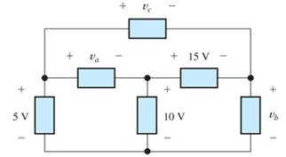
Figure P1.42
Expert Solution & Answer
Want to see the full answer?
Check out a sample textbook solution
Students have asked these similar questions
2. Suppose
G₁(s) = (s+2)
G₂(s) = (s-3)
C(s)
Find the transfer function G(s):
for each of the following three configurations
R(s)
shown in Figure 1. Note (a) is a cascaded (series) system, (b) is a parallel system, and
(c) is a feedback (closed-loop) system.
€
(c)
C(s)
R(s)
G₁(s)
G2(5)
G₁(s)
R(s)
C(s)
G2(s)
C(s)
R(s)
G₁(s)
G₂(s)
Figure 1
Determine the transformer's active power losses and primary voltage (Figure 1). The
busbar's voltage at the transformer's secondary side is 20.5 kV. Load P is 6 MW, and the
power factor is 0.95ind.
Select a short-circuit withstanding (1-second short circuit length) cable for Feeder 1 in
Figure 1. Values for cables are given in Table 1. The voltage of the supplying network is
now 115 kV and the short-circuit power of the supplying network is 2000 MVA.
Table 1. Technical information of 3-phase cables (10 kV and 20 kV)
Product's name
EA-number
Structural information
20KV
20KV
20 KV
0624250
0624252
0624253
0624254
AHKAMK-W AHKAMKW AHKAMKWAHKAMKW AHKAMKW AHKAMKW AHKAMKW
3x50Al+35Cu 3x95 Al. 35Cu 3x120Al. 35Cu 3x150Al+35Cu 3x185Al+35Cu 3x240A1+70 Cu 3x300Al+70Cu
20kV
20kV 20 kV (8) 20KV
0624255
0624257
0624256
Diameter of conductor
Diameter of out-most circle
Cable's outer diameter
Mass
Delivery information
Standard length
Delivery reel
mm
8.0
11.3
12.7
14.1
15.7
18.1
20.3
mm
28
32
34
35
37
40
43
mm
64
71
74
76
80
89
94
aluminium
kg/km
510
910
1100
1350
1650
2200
2700
сорраг
kg/km
305
305
305
305
305
600
600
cable
kg/km
2350
3100
3450
3800
4300
5500
6250
E
500
500
500
500
500
500
500…
Chapter 1 Solutions
Electrical Engineering: Principles & Applications (7th Edition)
Ch. 1 - Broadly speaking, what are the two main objectives...Ch. 1 - Prob. 1.2PCh. 1 - List eight subdivisions of electrical engineering.Ch. 1 - Prob. 1.4PCh. 1 - Prob. 1.5PCh. 1 - In the fluid-flow analogy for electrical circuits,...Ch. 1 - The charge of an electron is 1.601019C . A current...Ch. 1 - The ends of a length of wire are labeled a and b....Ch. 1 - The circuit element shown in Figure P1.9 has v=12V...Ch. 1 - Prob. 1.10P
Ch. 1 - The net charge through a cross section of a...Ch. 1 - The current through a particular circuit element...Ch. 1 - The current through a given circuit element is...Ch. 1 - The net charge through a cross section of a...Ch. 1 - A copper wire has a diameter of 2.05 mm and...Ch. 1 - A certain lead acid storage battery has a mass of...Ch. 1 - A circuit element having terminals a and b has...Ch. 1 - An electron moves through a voltage of 9 V from...Ch. 1 - A typical “deep-cycle” battery (used for electric...Ch. 1 - Define the term passive reference configuration....Ch. 1 - Compute the power for each element shown in Figure...Ch. 1 - The terminals of an electrical device are labeled...Ch. 1 - The terminals of a certain battery are labeled a...Ch. 1 - The element shown in Figure P1.24 I has v(t)=10V...Ch. 1 - The current and voltage of an electrical device...Ch. 1 - Suppose that the cost of electrical energy is...Ch. 1 - Figure P1.27 shows an ammeter (AM) and voltmeter...Ch. 1 - Repeat Problem P1.27 with the meters connected as...Ch. 1 - A certain type of D-cell battery that costs $0.50...Ch. 1 - The electronics aboard a certain sailboat consume...Ch. 1 - What s a node in an electrical circuit? Identify...Ch. 1 - State Kirchhoff’s current law.Ch. 1 - Two electrical elements are connected in series....Ch. 1 - Suppose that in the fluid-flow analogy for an...Ch. 1 - Identify elements that are in series in the...Ch. 1 - Consider the circuit shown in Figure P1.36. Which...Ch. 1 - Use KCL to find the values of ia, ic , and id for...Ch. 1 - Find the values of the other currents in Figure...Ch. 1 - Prob. 1.39PCh. 1 - State Kirchhoff’s voltage law.Ch. 1 - Consider the circuit shown in Figure P1.36. Which...Ch. 1 - Use KVL to solve for the voltages va , vb, and vc...Ch. 1 - Solve for the other voltages shown in Figure P1.43...Ch. 1 - Use KVL and KCL to solve for the labeled currents...Ch. 1 - Identify elements that are in parallel in Figure...Ch. 1 - Points a, b, c, and d appear in a certain circuit....Ch. 1 - In your own words, define an ideal conductor; an...Ch. 1 - Name four types of dependent sources and give the...Ch. 1 - State Ohm’s law, including references.Ch. 1 - Draw a circuit that contains a 5 resistance, a...Ch. 1 - Repeat Problem P1.50, placing all three elements...Ch. 1 - The resistance of a certain copper wire is 0.5. ....Ch. 1 - Draw a circuit that contains a 5 resistor, a 10-V...Ch. 1 - Draw a circuit that contains a 5 resistor, a 10-V...Ch. 1 - A power of 100 W is delivered to a certain...Ch. 1 - The voltage across a 10 resistor is given by...Ch. 1 - The voltage across a 10 resistor is given by...Ch. 1 - A certain wire has a resistance of 0.5 . Find the...Ch. 1 - Plot i versus v to scale for each of the parts of...Ch. 1 - Which of the following are self-contradictory...Ch. 1 - Consider the circuit shown in Figure P1.61. Find...Ch. 1 - Consider the circuit shown in Figure P1.62. Find...Ch. 1 - Consider the circuit shown in Figure P1.63. Find...Ch. 1 - Consider the circuit shown in Figure P1.64. Use...Ch. 1 - Determine the value of Ix in the circuit shown in...Ch. 1 - Consider the circuit shown in Figure P1.66. Figure...Ch. 1 - Prob. 1.67PCh. 1 - Consider the circuit shown in Figure P1.68. Figure...Ch. 1 - Solve for the currents shown in Figure P1.69....Ch. 1 - The circuit shown in Figure P1.70 contains a...Ch. 1 - Determine the value of vx and iy in the circuit...Ch. 1 - A 10-V independent voltage source is in series...Ch. 1 - A 10-V independent voltage source is in parallel...Ch. 1 - Consider the circuit shown in Figure P1.74. Figure...Ch. 1 - The circuit shown in Figure P1.75 contains a...Ch. 1 - For the circuit shown in Figure P1.76, solve for...Ch. 1 - For the circuit shown in Figure P1.77, solve for...Ch. 1 - Match each entry in Table T1.1(a) with the best...Ch. 1 - Prob. 1.2PTCh. 1 - The circuit of Figure T1.3 has I1=3A , I2=1A ,...Ch. 1 - The circuit shown in Figure T1.4 has Vs=12V ,...Ch. 1 - We are given Vs=15V , R=10 , and =0.3S for the...Ch. 1 - We are given i4=2A for the circuit of Figure T1.6....
Additional Engineering Textbook Solutions
Find more solutions based on key concepts
What types of coolant are used in vehicles?
Automotive Technology: Principles, Diagnosis, And Service (6th Edition) (halderman Automotive Series)
The solid steel shaft AC has a diameter of 25 mm and is supported by smooth bearings at D and E. It is coupled ...
Mechanics of Materials (10th Edition)
Assume a telephone signal travels through a cable at two-thirds the speed of light. How long does it take the s...
Electric Circuits. (11th Edition)
17–1C A high-speed aircraft is cruising in still air. How does the temperature of air at the nose of the aircra...
Thermodynamics: An Engineering Approach
This optional Google account security feature sends you a message with a code that you must enter, in addition ...
SURVEY OF OPERATING SYSTEMS
How are relationships between tables expressed in a relational database?
Modern Database Management
Knowledge Booster


Learn more about
Need a deep-dive on the concept behind this application? Look no further. Learn more about this topic, electrical-engineering and related others by exploring similar questions and additional content below.Similar questions
- A three-phase 20 kV medium-voltage line is 10 km. Resistance is 0.252 2/km and reactance is 0.128 92/km (inductive). Voltage at the beginning of line is 21.0 kV. At the end of the line is loading P = 2.5 MW with power factor 0.92ind. Draw 1-phase equivalent diagram and calculate line voltage at the end the of line, active and reactive power at the beginning of the line and power losses of the line.arrow_forwardA three-phase 20 kV medium-voltage line is 10 km. Resistance is 0.365 2/km and reactance is 0.363 2/km (inductive). Voltage at the beginning of line is 20.5 kV. At the end of the line is loading P= 800 kW with power factor 0.95ind. Draw 1-phase equivalent diagram and calculate load current, line voltage at the end the of line, voltage drop and power losses of the line.arrow_forward6. Answer the following questions. Take help from ChatGPT to answer these questions (if you need). Write the answers briefly using your own words with no more than two sentences, and make sure you check whether ChatGPT is giving you the appropriate answers in our context. A) What is a model in our context? B) What is an LTI system? C) What are the three forms of model we have used in the class so far to represent an LTI system? Among the above three forms, which forms can still be used to represent a nonlinear system?arrow_forward
- 5. Consider the following block diagram of a system in the Figure 4. Y₁(s) G₁ G2. R(s) C(s) Y₂(s) G3 G4 Figure 4 The models of the blocks G1, G2, G3 and G4 are represented by a differential equation, transfer function, state-space form, and impulse response as the followings. dy1 G₁: +2y₁ = 3r(t) dt 1 G2: G₂(s) = S+3 G3: x=2x+r, y2=3x-r G4: h(t)=8(t) + et 1(t) Find the simplified expression of the overall transfer function of the system i.e., G(s) = Note for G3 block, you may need to use the formula H(s) = C (sI - A)-¹ B+ D. C(s) R(s)arrow_forward4. Simplify the block diagram in Figure 3 and find the closed-loop transfer function G(s) = C(s) R(s) G₁ R(s) Figure 3 C(s) G2 H₁ H₂arrow_forward1. Consider a system defined by the following state-space equations. -5 2 N-MAN-G = 3 -1 y = [12] Find the transfer function H(s) = x1 x2. Y(s) U(s)' + 5arrow_forward
- 3. Simplify the block diagram in Figure 2 and find the closed-loop transfer function G(s) = C(s) R(s)' G₁ C(s) R(s) G2 G3 G4 Figure 2arrow_forwardRigid network supplies Feeder 1 through 110/21 kV transformer (Figure 1). Short circuit power of the supplying network is 5000 MVA and voltage is 110 kV. Determine 3-phase short circuit current for the point A. Draw 1-phase equivalent diagram. How big is the current if the 3-phase short circuit occurs in the Busbar? 110/21 kV Busbar Supplying network S = 16MVA 4-10% Figure 1. Feeder 1: 1-5km - r = 0.337 2/km x 0.361 2/km Aarrow_forwardRigid network supplies Feeder 1 through 110/21 kV transformer (Figure 1). Short circuit power of the supplying network is 3000 MVA and voltage is 110 kV. Length of feeder 1 is 5 km. Determine 3-phase short circuit current for the point A. Draw 1-phase equivalent diagram. 110/21 kV Busbar Supplying network S = 16MVA 4-10% Feeder 1: Figure 1. - 1 = 5km r = 0.337 2/km x = 0.361 2/km Aarrow_forward
arrow_back_ios
SEE MORE QUESTIONS
arrow_forward_ios
Recommended textbooks for you
 Delmar's Standard Textbook Of ElectricityElectrical EngineeringISBN:9781337900348Author:Stephen L. HermanPublisher:Cengage Learning
 Power System Analysis and Design (MindTap Course ...Electrical EngineeringISBN:9781305632134Author:J. Duncan Glover, Thomas Overbye, Mulukutla S. SarmaPublisher:Cengage Learning
Delmar's Standard Textbook Of Electricity
Electrical Engineering
ISBN:9781337900348
Author:Stephen L. Herman
Publisher:Cengage Learning
Power System Analysis and Design (MindTap Course ...
Electrical Engineering
ISBN:9781305632134
Author:J. Duncan Glover, Thomas Overbye, Mulukutla S. Sarma
Publisher:Cengage Learning
Introduction to Coulomb's Law or the Electric Force; Author: Flipping Physics;https://www.youtube.com/watch?v=4ubqby1Id4g;License: Standard YouTube License, CC-BY