
EBK ELECTRICAL ENGINEERING
7th Edition
ISBN: 8220106714201
Author: HAMBLEY
Publisher: YUZU
expand_more
expand_more
format_list_bulleted
Videos
Textbook Question
Chapter 1, Problem 1.77P
For the circuit shown in Figure P1.77, solve for the current
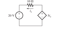
Figure P1.77
Expert Solution & Answer
Want to see the full answer?
Check out a sample textbook solution
Students have asked these similar questions
How do we know that D1 is forward bias and D2 is reverse biased?
Solve it in a different way than the previous solution that I searched for
A lossless uncharged transmission line of length L = 0.45 cm has a characteristic impedance of 60 ohms. It is driven by an ideal voltage generator producing a pulse of amplitude 10V and width 2 nS. If the transmission line is connected to a load of 200 ohms, sketch the voltage at the load as a function of time for the interval 0 < t < 20 nS. You may assume that the propagation velocity of the transmission is c/2. Answered now answer number 2.
Repeat Q.1 but now assume the width of the pulse produced by the generator is 4 nS. Sketch the voltage at the load as a function of time for 0 < t < 20 nS.
Chapter 1 Solutions
EBK ELECTRICAL ENGINEERING
Ch. 1 - Broadly speaking, what are the two main objectives...Ch. 1 - Prob. 1.2PCh. 1 - List eight subdivisions of electrical engineering.Ch. 1 - Prob. 1.4PCh. 1 - Prob. 1.5PCh. 1 - In the fluid-flow analogy for electrical circuits,...Ch. 1 - The charge of an electron is 1.601019C . A current...Ch. 1 - The ends of a length of wire are labeled a and b....Ch. 1 - The circuit element shown in Figure P1.9 has v=12V...Ch. 1 - Prob. 1.10P
Ch. 1 - The net charge through a cross section of a...Ch. 1 - The current through a particular circuit element...Ch. 1 - The current through a given circuit element is...Ch. 1 - The net charge through a cross section of a...Ch. 1 - A copper wire has a diameter of 2.05 mm and...Ch. 1 - A certain lead acid storage battery has a mass of...Ch. 1 - A circuit element having terminals a and b has...Ch. 1 - An electron moves through a voltage of 9 V from...Ch. 1 - A typical “deep-cycle” battery (used for electric...Ch. 1 - Define the term passive reference configuration....Ch. 1 - Compute the power for each element shown in Figure...Ch. 1 - The terminals of an electrical device are labeled...Ch. 1 - The terminals of a certain battery are labeled a...Ch. 1 - The element shown in Figure P1.24 I has v(t)=10V...Ch. 1 - The current and voltage of an electrical device...Ch. 1 - Suppose that the cost of electrical energy is...Ch. 1 - Figure P1.27 shows an ammeter (AM) and voltmeter...Ch. 1 - Repeat Problem P1.27 with the meters connected as...Ch. 1 - A certain type of D-cell battery that costs $0.50...Ch. 1 - The electronics aboard a certain sailboat consume...Ch. 1 - What s a node in an electrical circuit? Identify...Ch. 1 - State Kirchhoff’s current law.Ch. 1 - Two electrical elements are connected in series....Ch. 1 - Suppose that in the fluid-flow analogy for an...Ch. 1 - Identify elements that are in series in the...Ch. 1 - Consider the circuit shown in Figure P1.36. Which...Ch. 1 - Use KCL to find the values of ia, ic , and id for...Ch. 1 - Find the values of the other currents in Figure...Ch. 1 - Prob. 1.39PCh. 1 - State Kirchhoff’s voltage law.Ch. 1 - Consider the circuit shown in Figure P1.36. Which...Ch. 1 - Use KVL to solve for the voltages va , vb, and vc...Ch. 1 - Solve for the other voltages shown in Figure P1.43...Ch. 1 - Use KVL and KCL to solve for the labeled currents...Ch. 1 - Identify elements that are in parallel in Figure...Ch. 1 - Points a, b, c, and d appear in a certain circuit....Ch. 1 - In your own words, define an ideal conductor; an...Ch. 1 - Name four types of dependent sources and give the...Ch. 1 - State Ohm’s law, including references.Ch. 1 - Draw a circuit that contains a 5 resistance, a...Ch. 1 - Repeat Problem P1.50, placing all three elements...Ch. 1 - The resistance of a certain copper wire is 0.5. ....Ch. 1 - Draw a circuit that contains a 5 resistor, a 10-V...Ch. 1 - Draw a circuit that contains a 5 resistor, a 10-V...Ch. 1 - A power of 100 W is delivered to a certain...Ch. 1 - The voltage across a 10 resistor is given by...Ch. 1 - The voltage across a 10 resistor is given by...Ch. 1 - A certain wire has a resistance of 0.5 . Find the...Ch. 1 - Plot i versus v to scale for each of the parts of...Ch. 1 - Which of the following are self-contradictory...Ch. 1 - Consider the circuit shown in Figure P1.61. Find...Ch. 1 - Consider the circuit shown in Figure P1.62. Find...Ch. 1 - Consider the circuit shown in Figure P1.63. Find...Ch. 1 - Consider the circuit shown in Figure P1.64. Use...Ch. 1 - Determine the value of Ix in the circuit shown in...Ch. 1 - Consider the circuit shown in Figure P1.66. Figure...Ch. 1 - Prob. 1.67PCh. 1 - Consider the circuit shown in Figure P1.68. Figure...Ch. 1 - Solve for the currents shown in Figure P1.69....Ch. 1 - The circuit shown in Figure P1.70 contains a...Ch. 1 - Determine the value of vx and iy in the circuit...Ch. 1 - A 10-V independent voltage source is in series...Ch. 1 - A 10-V independent voltage source is in parallel...Ch. 1 - Consider the circuit shown in Figure P1.74. Figure...Ch. 1 - The circuit shown in Figure P1.75 contains a...Ch. 1 - For the circuit shown in Figure P1.76, solve for...Ch. 1 - For the circuit shown in Figure P1.77, solve for...Ch. 1 - Match each entry in Table T1.1(a) with the best...Ch. 1 - Prob. 1.2PTCh. 1 - The circuit of Figure T1.3 has I1=3A , I2=1A ,...Ch. 1 - The circuit shown in Figure T1.4 has Vs=12V ,...Ch. 1 - We are given Vs=15V , R=10 , and =0.3S for the...Ch. 1 - We are given i4=2A for the circuit of Figure T1.6....
Additional Engineering Textbook Solutions
Find more solutions based on key concepts
A nozzle at A discharges water with an initial velocity of 36 ft/s at an angle with the horizontal. Determine ...
Vector Mechanics For Engineers
This optional Google account security feature sends you a message with a code that you must enter, in addition ...
SURVEY OF OPERATING SYSTEMS
The solid steel shaft AC has a diameter of 25 mm and is supported by smooth bearings at D and E. It is coupled ...
Mechanics of Materials (10th Edition)
Why is the study of database technology important?
Database Concepts (8th Edition)
Assume a telephone signal travels through a cable at two-thirds the speed of light. How long does it take the s...
Electric Circuits. (11th Edition)
CONCEPT QUESTIONS
15.CQ3 The ball rolls without slipping on the fixed surface as shown. What is the direction ...
Vector Mechanics for Engineers: Statics and Dynamics
Knowledge Booster


Learn more about
Need a deep-dive on the concept behind this application? Look no further. Learn more about this topic, electrical-engineering and related others by exploring similar questions and additional content below.Similar questions
- Solve this experiment with an accurate solution, please. Thank you.arrow_forwardA lossless uncharged transmission line of characteristic impedance Zo = 600 and length T = 1us is connected to a 180 load. If this transmission line is connected at t = 0 to a 90 V dc source with an internal resistance of 900, from a bounce diagram of this system sketch (a) the voltage at z=0, z=L, and z = L/2 for up to 7.25μs and (b) calculate the load voltage after an infinite amount of time.arrow_forwardA lossless uncharged transmission line of length L = 0.45 cm has a characteristic impedance of 60 ohms. It is driven by an ideal voltage generator producing a pulse of amplitude 10V and width 2 nS. If the transmission line is connected to a load of 200 ohms, sketch the voltage at the load as a function of time for the interval 0 < t < 20 nS. You may assume that the propagation velocity of the transmission is c/2.arrow_forward
- The VSWR (Voltage Standing Wave Ratio) is measured to be 2 on a transmission line. Find two values of the reflection coefficient with one corresponding to Z > Zo and the other to Zarrow_forwardA dc voltage of unknown value Vand internal resistance Reis connected through a switch to a lossless transmission line of Zo = 1000. If the first 5 μS of the voltages at z = 0 and z = L are observed to be as shown below, calculate Vo, RG, the load resistanceR,, and the transit time T. 100 + [V]:-0. V 90 [V]:-V 100 75 I, Տ 1,μs 2 4 6 0 2 4 6arrow_forwardA lossless open circuited transmission line behaves as an equivalent capacitance of Ceq = Tan (BL) Show for BL << 1 that Ceq = C'L where L is the length of the transmission line and wZo C' is the lumped parameter capacitance per unit length of the transmission line. Hint: For x small, Tan(x) = x.arrow_forward= A generator with VG 300V and R = 50 is connected to a load R = 750 through a 50 lossless transmission line of length L = 0.15 m. (a) Compute Zin, the input impedance of the line at the generator end. (b) Compute and V. (c) Compute the time-average power Pin delivered to the line. (d) Compute VL, IL, and the time-average power delivered to the load, PL (e) How does Pin compare to PL? Explain.arrow_forwardFor the regulated power supply circuit, assume regular diodes with 0.7V forward drop. Use a 15V (peak), 60Hz sine wave at the transformer secondary and assume a maximum ripple level of 1V. (a) Compute the unknown components needed to design 10V DC supply.Hint: find R first, and then C. What is the ripple level for C=22µF?Sketch the rectified, filtered, and regulated outputsarrow_forwardA) Find the solution of B) Find the convolution of Sewt (t-π)dt 8 e-atu(t)e-blu(t)arrow_forwardConsider the signal: f(t)= 0, ㅠ 1 Use the Fourier transform formula to find F(w). otherwisearrow_forwardA half-wave controlled rectifier is supplied by a 230 Vrms voltage source and has load resistance of 2502. Calculate the delay angle a that produces a load-absorbed power of 200W.arrow_forwardQ6 The FET shown in Fig. 1.43 has gm = 3.4 mS and rd =100 K. Find the approximate lower cutoff frequency. Ans: 735.1 Hz. 25V 1.5ΜΩ 20 ΚΩ 0.02µF HH 2ΚΩ 0.02µF HH 330kQ 820 ΩΣ 1.0µF www 40ΚΩarrow_forwardarrow_back_iosSEE MORE QUESTIONSarrow_forward_ios
Recommended textbooks for you
 Introductory Circuit Analysis (13th Edition)Electrical EngineeringISBN:9780133923605Author:Robert L. BoylestadPublisher:PEARSON
 Delmar's Standard Textbook Of ElectricityElectrical EngineeringISBN:9781337900348Author:Stephen L. HermanPublisher:Cengage Learning
 Programmable Logic ControllersElectrical EngineeringISBN:9780073373843Author:Frank D. PetruzellaPublisher:McGraw-Hill Education
 Fundamentals of Electric CircuitsElectrical EngineeringISBN:9780078028229Author:Charles K Alexander, Matthew SadikuPublisher:McGraw-Hill Education
 Electric Circuits. (11th Edition)Electrical EngineeringISBN:9780134746968Author:James W. Nilsson, Susan RiedelPublisher:PEARSON
 Engineering ElectromagneticsElectrical EngineeringISBN:9780078028151Author:Hayt, William H. (william Hart), Jr, BUCK, John A.Publisher:Mcgraw-hill Education,
Introductory Circuit Analysis (13th Edition)
Electrical Engineering
ISBN:9780133923605
Author:Robert L. Boylestad
Publisher:PEARSON
Delmar's Standard Textbook Of Electricity
Electrical Engineering
ISBN:9781337900348
Author:Stephen L. Herman
Publisher:Cengage Learning
Programmable Logic Controllers
Electrical Engineering
ISBN:9780073373843
Author:Frank D. Petruzella
Publisher:McGraw-Hill Education
Fundamentals of Electric Circuits
Electrical Engineering
ISBN:9780078028229
Author:Charles K Alexander, Matthew Sadiku
Publisher:McGraw-Hill Education
Electric Circuits. (11th Edition)
Electrical Engineering
ISBN:9780134746968
Author:James W. Nilsson, Susan Riedel
Publisher:PEARSON
Engineering Electromagnetics
Electrical Engineering
ISBN:9780078028151
Author:Hayt, William H. (william Hart), Jr, BUCK, John A.
Publisher:Mcgraw-hill Education,
Lesson 2 - Source Transformations, Part 2 (Engineering Circuits); Author: Math and Science;https://www.youtube.com/watch?v=7gno74RhVGQ;License: Standard Youtube License