
EP ELECTRICAL ENGR.-MODIF.MASTERINGENGR
7th Edition
ISBN: 9780134486994
Author: HAMBLEY
Publisher: PEARSON CO
expand_more
expand_more
format_list_bulleted
Concept explainers
Videos
Textbook Question
Chapter 1, Problem 1.70P
The circuit shown in Figure P1.70 contains a voltage-controlled voltage source.
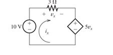
Figure P1.70
- Use KVL to write an equation relating the voltages and solve for vx.
Expert Solution & Answer
Want to see the full answer?
Check out a sample textbook solution
Students have asked these similar questions
Question 2
A transistor is used as a switch and the waveforms are shown in Figure 2. The parameters are
Vcc = 225 V, VBE(sat) = 3 V, IB = 8 A, VCE(sat) = 2 V, Ics = 90 A, td = 0.5 µs, tr = 1 µs, ts = 3 µs, tƒ
= 2 μs, and f
10 kHz. The duty cycle is k 50%. The collector- emitter leakage current is
ICEO = 2 mA. Determine the power loss due to the collector current:
=
=
=
(a) during turn-on ton = td + tr
VCE
Vcc
(b) during conduction period tn
V CE(sat)
0
toff"
ton
Ics
0.9 Ics
(c) during turn-off toff = ts + tf
(d) during off-time tot
(e) the total average power losses PT
ICEO
0
IBS
0
Figure 2
V BE(sat)
0
主
*
td
tr
In
Is
If
to
iB
VBE
T= 1/fs
Question 1:
The beta (B) of the bipolar transistor shown in Figure 1 varies from 12 to 60. The load resistance
is Rc = 5. The dc supply voltage is VCC = 40 V and the input voltage to the base circuit is
VB = 5 V. If VCE(sat) = 1.2 V, VBE(sat) = 1.6 V, and RB = 0.8 2, calculate:
(a) the overdrive factor ODF.
(b) the forced ẞ
(c) the power loss in the transistor PT.
IB
VB
RB
+
V BE
RC
Vcc'
Ic
+
IE
Figure 1
VCE
I need help in creating a matlab code to find the currents
Chapter 1 Solutions
EP ELECTRICAL ENGR.-MODIF.MASTERINGENGR
Ch. 1 - Broadly speaking, what are the two main objectives...Ch. 1 - Prob. 1.2PCh. 1 - List eight subdivisions of electrical engineering.Ch. 1 - Prob. 1.4PCh. 1 - Prob. 1.5PCh. 1 - In the fluid-flow analogy for electrical circuits,...Ch. 1 - The charge of an electron is 1.601019C . A current...Ch. 1 - The ends of a length of wire are labeled a and b....Ch. 1 - The circuit element shown in Figure P1.9 has v=12V...Ch. 1 - Prob. 1.10P
Ch. 1 - The net charge through a cross section of a...Ch. 1 - The current through a particular circuit element...Ch. 1 - The current through a given circuit element is...Ch. 1 - The net charge through a cross section of a...Ch. 1 - A copper wire has a diameter of 2.05 mm and...Ch. 1 - A certain lead acid storage battery has a mass of...Ch. 1 - A circuit element having terminals a and b has...Ch. 1 - An electron moves through a voltage of 9 V from...Ch. 1 - A typical “deep-cycle” battery (used for electric...Ch. 1 - Define the term passive reference configuration....Ch. 1 - Compute the power for each element shown in Figure...Ch. 1 - The terminals of an electrical device are labeled...Ch. 1 - The terminals of a certain battery are labeled a...Ch. 1 - The element shown in Figure P1.24 I has v(t)=10V...Ch. 1 - The current and voltage of an electrical device...Ch. 1 - Suppose that the cost of electrical energy is...Ch. 1 - Figure P1.27 shows an ammeter (AM) and voltmeter...Ch. 1 - Repeat Problem P1.27 with the meters connected as...Ch. 1 - A certain type of D-cell battery that costs $0.50...Ch. 1 - The electronics aboard a certain sailboat consume...Ch. 1 - What s a node in an electrical circuit? Identify...Ch. 1 - State Kirchhoff’s current law.Ch. 1 - Two electrical elements are connected in series....Ch. 1 - Suppose that in the fluid-flow analogy for an...Ch. 1 - Identify elements that are in series in the...Ch. 1 - Consider the circuit shown in Figure P1.36. Which...Ch. 1 - Use KCL to find the values of ia, ic , and id for...Ch. 1 - Find the values of the other currents in Figure...Ch. 1 - Prob. 1.39PCh. 1 - State Kirchhoff’s voltage law.Ch. 1 - Consider the circuit shown in Figure P1.36. Which...Ch. 1 - Use KVL to solve for the voltages va , vb, and vc...Ch. 1 - Solve for the other voltages shown in Figure P1.43...Ch. 1 - Use KVL and KCL to solve for the labeled currents...Ch. 1 - Identify elements that are in parallel in Figure...Ch. 1 - Points a, b, c, and d appear in a certain circuit....Ch. 1 - In your own words, define an ideal conductor; an...Ch. 1 - Name four types of dependent sources and give the...Ch. 1 - State Ohm’s law, including references.Ch. 1 - Draw a circuit that contains a 5 resistance, a...Ch. 1 - Repeat Problem P1.50, placing all three elements...Ch. 1 - The resistance of a certain copper wire is 0.5. ....Ch. 1 - Draw a circuit that contains a 5 resistor, a 10-V...Ch. 1 - Draw a circuit that contains a 5 resistor, a 10-V...Ch. 1 - A power of 100 W is delivered to a certain...Ch. 1 - The voltage across a 10 resistor is given by...Ch. 1 - The voltage across a 10 resistor is given by...Ch. 1 - A certain wire has a resistance of 0.5 . Find the...Ch. 1 - Plot i versus v to scale for each of the parts of...Ch. 1 - Which of the following are self-contradictory...Ch. 1 - Consider the circuit shown in Figure P1.61. Find...Ch. 1 - Consider the circuit shown in Figure P1.62. Find...Ch. 1 - Consider the circuit shown in Figure P1.63. Find...Ch. 1 - Consider the circuit shown in Figure P1.64. Use...Ch. 1 - Determine the value of Ix in the circuit shown in...Ch. 1 - Consider the circuit shown in Figure P1.66. Figure...Ch. 1 - Prob. 1.67PCh. 1 - Consider the circuit shown in Figure P1.68. Figure...Ch. 1 - Solve for the currents shown in Figure P1.69....Ch. 1 - The circuit shown in Figure P1.70 contains a...Ch. 1 - Determine the value of vx and iy in the circuit...Ch. 1 - A 10-V independent voltage source is in series...Ch. 1 - A 10-V independent voltage source is in parallel...Ch. 1 - Consider the circuit shown in Figure P1.74. Figure...Ch. 1 - The circuit shown in Figure P1.75 contains a...Ch. 1 - For the circuit shown in Figure P1.76, solve for...Ch. 1 - For the circuit shown in Figure P1.77, solve for...Ch. 1 - Match each entry in Table T1.1(a) with the best...Ch. 1 - Prob. 1.2PTCh. 1 - The circuit of Figure T1.3 has I1=3A , I2=1A ,...Ch. 1 - The circuit shown in Figure T1.4 has Vs=12V ,...Ch. 1 - We are given Vs=15V , R=10 , and =0.3S for the...Ch. 1 - We are given i4=2A for the circuit of Figure T1.6....
Additional Engineering Textbook Solutions
Find more solutions based on key concepts
Which of the following are illegal variable names in Python, and why? x 99bottles july2009 theSalesFigureForFis...
Starting Out with Python (4th Edition)
This optional Google account security feature sends you a message with a code that you must enter, in addition ...
SURVEY OF OPERATING SYSTEMS
What is an uninitialized variable?
Starting Out with Programming Logic and Design (5th Edition) (What's New in Computer Science)
The job of the _____ is to fetch instructions, carry out the operations commanded by the instructions, and prod...
Starting Out With Visual Basic (8th Edition)
Using your text editor, enter (that is, type in) the C++ program shown in Display 1.8. Be certain to type the f...
Problem Solving with C++ (10th Edition)
Computers process data under the control of sets of instructions called
Java How to Program, Early Objects (11th Edition) (Deitel: How to Program)
Knowledge Booster


Learn more about
Need a deep-dive on the concept behind this application? Look no further. Learn more about this topic, electrical-engineering and related others by exploring similar questions and additional content below.Similar questions
- I need help fixing this MATLAB code: as I try to get it working there were some problems:arrow_forwardI need help in construct a matlab code to find the voltage of VR1 to VR4, the currents, and the watts based on that circuit.arrow_forwardQ2: Using D flip-flops, design a synchronous counter. The counter counts in the sequence 1,3,5,7, 1,7,5,3,1,3,5,7,.... when its enable input x is equal to 1; otherwise, the counter count 0.arrow_forward
- From the collector characteristic curves and the dc load line given below, determine the following: (a) Maximum collector current for linear operation (b) Base current at the maximum collector current (c) VCE at maximum collector current. lc (mA) 600 ΜΑ 60- 500 με 50- 400 με 40- 300 μ Α 30- Q-point 200 ΜΑ 20- 10- 100 μ Α 0 VCE (V) 1 2 3 4 5 6 7 8 9 10 [6 Paarrow_forwardProcedure:- 1- Connect the cct. shown in fig.(2). a ADDS DS Fig.(2) 2-For resistive load, measure le output voltage by using oscilloscope ;then sketch this wave. 3- Measure the average values ::f VL and IL: 4- Repeat steps 2 & 3 but for RL load. Report:- 1- Calculate the D.C. output vcl age theoretically and compare it with the test value. 2- Calculate the harmonic cont :nts of the load voltage, and explain how filter components may be selected. 3- Compare between the three-phase half & full-wave uncontrolled bridge rectifier. 4- Draw the waveform for the c:t. shown in fig.(2) but after replaced Di and D3 by thyristors with a 30° and a2 = 90° 5- Draw the waveform for the cct. shown in fig.(2) but after replace the 6-diodes by 6- thyristor. 6- Discuss your results. Please solve No. 4 and 5arrow_forwardPlease I want solution by handwrittenarrow_forward
- 8 00 ! Required information Consider the circuit given below. 0/2 points awarded 3 ΚΩ www t=0 6kM Scored R 1.5i Vc 1 μF 10 V If R = 5.00 kQ, determine vao+). The value of va(0) is 1.4545 V.arrow_forwardI want to know what does it look in a breadboard circuit, because I want to created it but I not sure it is build properly, can you give me an illustuation base on this image, it do need to real, something like virutal examplearrow_forwardCharge neutrality Since doped semiconductor remains electroneutral, the concentration of negative charges equals the concentration of positive charges. n+ Na,ionized p+Nd,ionized np = n; 2 2 N-Na N N d d р + 2 2 n = Nd-Na 2 + Na - 2 Na +n₁ 2 71/2 1/2 2 2 +n Concentration of electrons and holes 1. Calculate concentrations of electrons and holes at room temperature in Si and Ge with donor concentration of 1.5x10¹7 cm³ and acceptor concentration of 8x1016 cm-3. 2. Will these concentrations change much with the temperature increase to 100°C?arrow_forward
- Answer the questions on the end of the image pleasearrow_forwardAnswer these two questions on the end of the image, please 1.Calculate intrinsic carrier concentration for Si, Ge and GaAs at temperatures -20°C, 20°C (room temperature) and 120°C 2.Compare the obtained data with n and p shown on previous slide 25arrow_forwardCan you help me achieve the requirements using Arduino? I have encountered some issues with these requirements. Q.2: Suppose you have two push buttons connected to ports (0 & 1) and four LED's connected to ports (6-9). Write a program to flash ON the odd LED's if we press the switch 0 for 4s, flash ON the even LED's if we press the switch 1 for 5s and flash ON all the LED's otherwise for 6s.arrow_forward
arrow_back_ios
SEE MORE QUESTIONS
arrow_forward_ios
Recommended textbooks for you
 Delmar's Standard Textbook Of ElectricityElectrical EngineeringISBN:9781337900348Author:Stephen L. HermanPublisher:Cengage Learning
Delmar's Standard Textbook Of Electricity
Electrical Engineering
ISBN:9781337900348
Author:Stephen L. Herman
Publisher:Cengage Learning
Kirchhoff's Rules of Electrical Circuits; Author: Flipping Physics;https://www.youtube.com/watch?v=d0O-KUKP4nM;License: Standard YouTube License, CC-BY