
Concept explainers
Videos
Scanning Confocal Microscopy
Although modern microscopes are marvels of optical engineering, their basic design is not too different from the 1665 compound microscope of Robert Hooke. Recently, advances in optics, lasers, and computer technology have made practical a new kind of optical microscope, the scanning confocal microscope. This microscope is capable of taking images of breathtaking clarity.
The figure shows the microscope’s basic principle of operation. The left part of the figure shows how the translucent specimen is illuminated by light from a laser. The laser beam is converted to a diverging bundle of rays by suitable optics, reflected off a mirror, then directed through a microscope objective lens to a focus within the sample. The microscope objective focuses the laser beam to a very small (≈ 0.5 μm) spot. Note that light from the laser passes through other regions of the specimen but, because the rays are not focused in those regions, they are not as intensely illuminated as is the point at the focus. This is the first important aspect of the design: Very intensely illuminate one very small volume of the sample while leaving other regions only weakly illuminated.
As shown in the right half of the figure, light is reflected from all illuminated points in the sample and passes back through the objective lens. The mirror that had reflected the laser light downward is actually a partially transparent
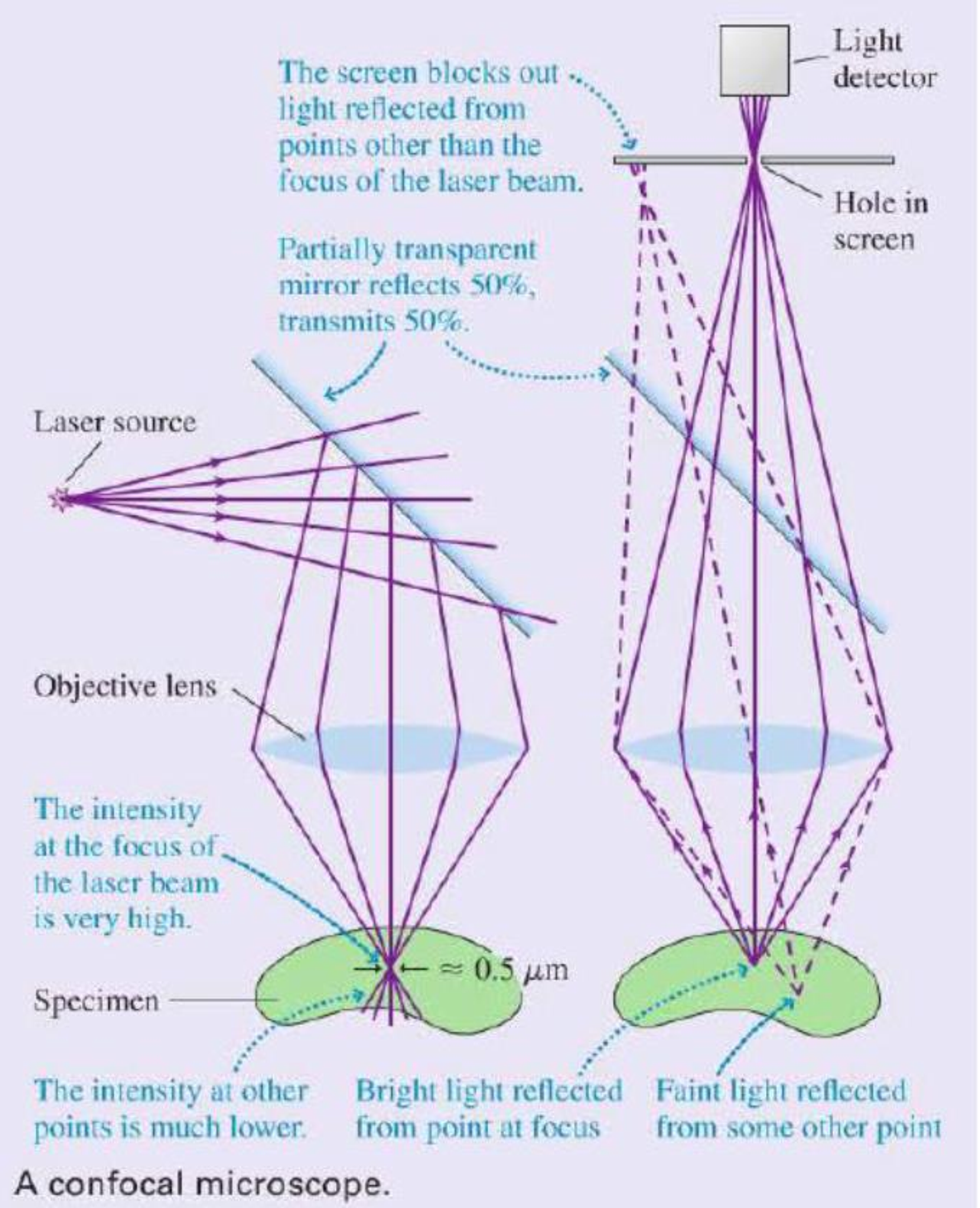
mirror that reflects 50% of the light and transmits 50%. Thus half of the light reflected upward from the sample passes through the mirror and is focused on a screen containing a small hole. Because of the hole, only light rays that emanate from the brightly illuminated volume in the sample can completely pass through the hole and reach the light detector behind it. Rays from other points in the sample either miss the hole completely or are out of locus when they reach the screen, so that only a small fraction of them pass through the hole. This second key design aspect limits the detected light to only those rays that are emitted from the point in the sample at which the laser light was originally focused.
So we see that (a) the point in the sample that is at the focus of the objective is much more intensely illuminated than any other point, so it reflects more rays than any other point, and (b) the hole serves to further limit the detected rays to only those that emanate from the focus. Taken together, these design aspects ensure the detected light comes from a very small, very well-defined volume in the sample.
The microscope as shown would only be useful for examining one small point in the sample. To make an actual image, the objective is scanned across the sample while the intensity is recorded by a computer. This procedure builds up an image of the sample one scan line at a time. The final result is a picture of the sample in the very narrow plane in which the laser beam is focused. Different planes within the sample can be imaged by moving the objective up or down before scanning. It is actually possible to make three dimensional images of a specimen in this way.
The improvement in contrast and resolution over conventional microscopy can be striking. The images show a section of a mouse kidney taken using conventional and confocal microscopy. Because light reflected from all parts of the specimen reaches the camera in a conventional microscope, that image appears blurred and has low contrast. The confocal microscope image represents a single plane or slice of the sample, and many details become apparent that are invisible in the conventional image.

A section of fluorescently stained mouse kidney imaged using standard optical microscopy (left) and scanning confocal microscopy (right).
The following questions are related to the passage “Scanning Con focal Microscopy” on the previous page.
1. A laser beam consists of parallel rays of light. To convert this light to the diverging rays required for a scanning confocal microscope requires
- A. A converging lens.
- B. A diverging lens.
- C. Either a converging or a diverging lens.
Want to see the full answer?
Check out a sample textbook solution
Chapter P Solutions
College Physics: A Strategic Approach (4th Edition)
Additional Science Textbook Solutions
Cosmic Perspective Fundamentals
Microbiology: An Introduction
Campbell Biology in Focus (2nd Edition)
Organic Chemistry (8th Edition)
Human Anatomy & Physiology (2nd Edition)
Human Physiology: An Integrated Approach (8th Edition)


- Formant Freqmcy The horizontal dotted lines represent the formants. The first box represents the schwa sound. The second box is a different vowel. The scale is the same on each of these two vowels. Use the two formant contours to answer questions 12-16 SCHWA VOWEL 2 0.179362213 Time (s) 0.92125285 0.0299637119 4000 1079 Time(s) unknown 0.6843 13. Please describe what the tongue is doing to shift from the schwa to vowel 2? 14. Is vowel 2 a rounded or unrounded vowel? 15. Is vowel 2 a front or back vowel? 16. What vowel is vowel 2 (00, ee, ah) 0684285714arrow_forwardmicrowavearrow_forward4) Consider the pulley (Mass = 20kg, Radius 0.3m) shown in the picture. Model this pulley as a uniform solid disk (1 = (1/2) MR2) that is hinged at its center of mass. If the hanging mass is 30 kg, and is released, (a) compute the angular acceleration of the pulley (b) calculate the acceleration of the hanging mass. A o 0.3 3019 20KSarrow_forward
- Refer to the image attachedarrow_forwardShrinking Loop. A circular loop of flexible iron wire has an initial circumference of 161 cm , but its circumference is decreasing at a constant rate of 15.0 cm/s due to a tangential pull on the wire. The loop is in a constant uniform magnetic field of magnitude 1.00 T , which is oriented perpendicular to the plane of the loop. Assume that you are facing the loop and that the magnetic field points into the loop. Find the magnitude of the emf E induced in the loop after exactly time 9.00 s has passed since the circumference of the loop started to decrease. Find the direction of the induced current in the loop as viewed looking along the direction of the magnetic field. Please explain all stepsarrow_forwardMake up an application physics principle problem that provides three (3) significant equations based on the concepts of capacitors and ohm's law.arrow_forward
- A straight horizontal garden hose 38.0 m long with an interior diameter of 1.50 cm is used to deliver 20oC water at the rate of 0.590 liters/s. Assuming that Poiseuille's Law applies, estimate the pressure drop (in Pa) from one end of the hose to the other.arrow_forwardA rectangle measuring 30.0 cm by 40.0 cm is located inside a region of a spatially uniform magnetic field of 1.70 T , with the field perpendicular to the plane of the coil (the figure (Figure 1)). The coil is pulled out at a steady rate of 2.00 cm/s traveling perpendicular to the field lines. The region of the field ends abruptly as shown. Find the emf induced in this coil when it is all inside the field, when it is partly in the field, and when it is fully outside. Please show all steps.arrow_forwardA rectangular circuit is moved at a constant velocity of 3.00 m/s into, through, and then out of a uniform 1.25 T magnetic field, as shown in the figure (Figure 1). The magnetic field region is considerably wider than 50.0 cm . Find the direction (clockwise or counterclockwise) of the current induced in the circuit as it is going into the magnetic field (the first case), totally within the magnetic field but still moving (the second case), and moving out of the field (the third case). Find the magnitude of the current induced in the circuit as it is going into the magnetic field . Find the magnitude of the current induced in the circuit as it is totally within the magnetic field but still moving. Find the magnitude of the current induced in the circuit as it is moving out of the field. Please show all stepsarrow_forward
- Shrinking Loop. A circular loop of flexible iron wire has an initial circumference of 161 cm , but its circumference is decreasing at a constant rate of 15.0 cm/s due to a tangential pull on the wire. The loop is in a constant uniform magnetic field of magnitude 1.00 T , which is oriented perpendicular to the plane of the loop. Assume that you are facing the loop and that the magnetic field points into the loop. Find the magnitude of the emf E induced in the loop after exactly time 9.00 s has passed since the circumference of the loop started to decrease. Find the direction of the induced current in the loop as viewed looking along the direction of the magnetic field. Please explain all stepsarrow_forwardA circular loop of wire with radius 0.0480 m and resistance 0.163 Ω is in a region of spatially uniform magnetic field, as shown in the following figure (Figure 1). The magnetic field is directed out of the plane of the figure. The magnetic field has an initial value of 7.88 T and is decreasing at a rate of -0.696 T/s . Is the induced current in the loop clockwise or counterclockwise? What is the rate at which electrical energy is being dissipated by the resistance of the loop? Please explain all stepsarrow_forwardA 0.333 m long metal bar is pulled to the left by an applied force F and moves to the left at a constant speed of 5.90 m/s. The bar rides on parallel metal rails connected through a 46.7 Ω resistor, as shown in (Figure 1), so the apparatus makes a complete circuit. You can ignore the resistance of the bar and rails. The circuit is in a uniform 0.625 T magnetic field that is directed out of the plane of the figure. Is the induced current in the circuit clockwise or counterclockwise? What is the rate at which the applied force is doing work on the bar? Please explain all stepsarrow_forward
 University Physics Volume 3PhysicsISBN:9781938168185Author:William Moebs, Jeff SannyPublisher:OpenStax
 Physics for Scientists and Engineers: Foundations...PhysicsISBN:9781133939146Author:Katz, Debora M.Publisher:Cengage Learning
 Principles of Physics: A Calculus-Based TextPhysicsISBN:9781133104261Author:Raymond A. Serway, John W. JewettPublisher:Cengage Learning
 Glencoe Physics: Principles and Problems, Student...PhysicsISBN:9780078807213Author:Paul W. ZitzewitzPublisher:Glencoe/McGraw-Hill
 Physics for Scientists and Engineers with Modern ...PhysicsISBN:9781337553292Author:Raymond A. Serway, John W. JewettPublisher:Cengage Learning