
Concept explainers
Videos
(a)
The principal mass moment of inertias at the origin.
Answer to Problem B.74P
The principal mass moment of inertias at the origin are
Explanation of Solution
Given information:
The mass per unit length of the steel is
Draw the diagram for the different section of the body.
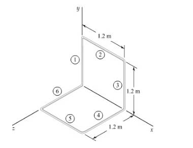
Figure-(1)
Concept used:
Write the expression for the mass of each section.
Here, the mass per unit length is
Write the expression of mass moment of inertia of section 1 about
Write the expression of mass moment of inertia of section 2 about
Write the expression of total mass moment of inertia about
Here, the mass moment of inertia for section 3 about x- axis is
The mass moment of inertia for section 1 is equal to the mass moment of inertia for section 3.
The mass moment of inertia for section 1 is equal to the mass moment of inertia for section 4.
The mass moment of inertia for section 1 is equal to the mass moment of inertia for section 6.
The mass moment of inertia for section 2 is equal to the mass moment of inertia for section 5.
Substitute
Write the expression of total mass moment of inertia about
Here, the mass moment of inertia for section 3 about y- axis is
The mass moment of inertia for section 1 is equal to zero.
The mass moment of inertia for section 4 is equal to the mass moment of inertia for section 5.
The mass moment of inertia for section 2 is equal to the mass moment of inertia for section 6.
Substitute
Write the expression of mass moment of inertia of section 2 about
Write the expression of mass moment of inertia of section 3 about
Write the expression of mass moment of inertia of section 4 about
The figure below illustrates the centroidal axis of a component.
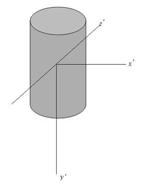
Figure-(2)
From the symmetry in above figure about
Here, the product mass moment of inertia in
From the symmetry in the above figure about
Here, the product mass moment of inertia in
From the symmetry in the above figure about
Here, the product mass moment of inertia in
Write the expression for product of mass moment of inertia in
Here, the product mass moment of inertia is
Write the expression for product mass moment of inertia in
Here, the product mass moment of inertia is
Write the expression for product mass moment of inertia in
Here, the product mass moment of inertia in
Write the expression of mass moment of inertia with respect o origin along the unit vector
Here, the mass moment of inertia with respect to origin along unit vector
Calculation:
Substitute
Substitute
Substitute
Substitute
Substitute
Substitute
Substitute
Substitute
The mass moment of inertia about z- axis and the mass moment of inertia about y- axis is equal due to symmetry.
Hence,
Substitute
Substitute
Substitute
After solving the above equation,
Conclusion:
The principal mass moment of inertias at the origin are
(b)
The principal axis about the origin.
Answer to Problem B.74P
The principal axis about the origin are
Explanation of Solution
Given information:
The mass per unit length of the steel is
Draw the diagram for the different section of the body.

Figure-(1)
Calculation:
The direction cosine is calculated as follows:
Substitute the values from the sub-part (a) in above equations as follows:
After solving above equations,
Direction cosine in x direction is calculated as follows:
Direction cosine in y and z direction are,
So, the direction is calculated as follows:
Again,
The direction cosine is calculated as follows:
Substitute the values from the sub-part (a) in above equations as follows:
After solving above equations,
Direction cosine in x direction is calculated as follows:
Direction cosine in z direction is,
So, the direction is calculated as follows:
Similarly,
The direction cosine is calculated as follows:
Substitute the values from the sub-part (a) in above equations as follows:
After solving above equations,
Direction cosine in x direction is calculated as follows:
Direction cosine in y and z direction are,
So, the direction is calculated as follows:
The sketch is shown below:
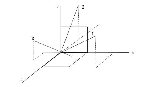
Conclusion:
So, the principal axis about the origin are
Want to see more full solutions like this?
Chapter B Solutions
Vector Mechanics For Engineers


- Auto Controls Design a proportional derivitivecontroller for a plant orsystemthat satisfies the following specifications : 1. is steady-state error is less than 2 % for a ramp input. 2.) Damping ratio (zeta) is greater than 0.7have determined the 3. Once youvalue of kp and kd, then plotthe response of the compensated(with controller) and uncompensated( without the controller, only the plantsystem using MATLAB.arrow_forwardAuto Controls (a) Refer to the above figure .What kind of controller is it ? (b) simplify the block diagramto derive the closed loop transfer function of the system. (C) What are the assumptions thatare needed to make to findthe controller gain ? What arethe value of Kp , Ti and Td ?arrow_forwardAuto Controls Design a PID controller for thefollowing system so that the modified system satisfies the followingspecifications : 1. settling time ,ts = 1.96 s and % Overshoot Mp = 70.7 % Assume a non-dominant pole at s = -15 to solve the problem The plot the compensated andThen plot the uncompensated system in MATLAB. what can you see from the plot ? what is your observation ?arrow_forward
- Fourth year Monthly exam\3 2024-2025 Power plant Time: 1 Hr Q1. A gas turbine power plant operates on a modified Brayton cycle consisting of two-stage compression with intercooling to the initial temperature between stages, two-stage expansion with reheating to the maximum cycle temperature, and two regenerative heat exchangers. The following data is given: Inlet air temperature: 300 K Maximum cycle temperature: 1400 K Pressure ratio across each compressor stage: 4 Pressure ratio across each turbine stage: 4 Isentropic efficiency of compressors and turbines: 85% Effectiveness of each regenerator: 80% a) Draw a schematic and T-s diagram of the cycle. b) Determine the thermal efficiency of the cycle. c) Calculate the net specific work output (in kJ/kg). d) Discuss the impact of regenerators on the cycle performance. Examiner Prof. Dr. Adil Al-Kumaitarrow_forwardAuto Controls The figure is a schematic diagram of an aircraft elevator control system. The input to the systemin the deflection angle of the control lever , and the output is the elevator angle phi.show that for each angle theta of the control lever ,there is a corresponding elevator angle phi. Then find Y(s)/theta(s) and simplify the resulting transfer function . Also note from the diagram that y and phi is relatedarrow_forwardLiquid hexane flows through a counter flow heat exchanger at 5 m3/h as shown in Figure E5.5.The hexane enters the heat exchanger at 90°C. Water, flowing at 5 m3/h, is used to cool the hexane.The water enters the heat exchanger at 15°C. The UA product of the heat exchanger is found to be2.7 kW/K. Determine the outlet temperatures of the hot and cold fluids and the heat transfer ratebetween them using LMTD method.arrow_forward
- Determine the fluid outlet temperatures and the heat transfer rate for the counter flow heatexchanger described in Problem 3 using the ε-NTU model. Assume that the properties can beevaluated at the given fluid inlet temperatures.arrow_forwardSection View - practice Homework 0.5000 3.0000 2,0000 1.0000arrow_forwardDrawing the section view for the following multiview drawing AutoCAD you see the section pratice I need to show how to autocadarrow_forward
- A boiler with 80% efficiency produces steam at 40bar and 500 C at a rate of 1.128kg/s. The temperature of the feed water is raised from 25 C to 125 C in the economizer and the ambient air is drawn to the boiler at a rate of 2.70 kg/s at 16 C. The flue gases leave the chimney at rate of 3 kg/s at 150 C with specific heat of 1.01 kJ/kg.K. The dryness fraction of steam collected in the steam drum is 0.95. 1- Determine the heat value of the fuel. 2- The equivalence evaporation. 3- Draw the heat balance sheet.arrow_forwardA rotating shaft is made of 42 mm by 4 mm thick cold-drawn round steel tubing and has a 6 mm diameter hole drilled transversely through it. The shaft is subjected to a pulsating torque fluctuating from 20 to 160 Nm and a completely reversed bending moment of 200 Nm. The steel tubing has a minimum strength of Sut = 410 MPa (60 ksi). The static stress-concentration factor for the hole is 2.4 for bending and 1.9 for torsion. The maximum operating temperature is 400˚C and a reliability of 99.9% is to be assumed. Find the factor of safety for infinite life using the modified Goodman failure criterion.arrow_forwardI need help with a MATLAB code. This code just keeps running and does not give me any plots. I even reduced the tolerance from 1e-9 to 1e-6. Can you help me fix this? Please make sure your solution runs. % Initial Conditions rev = 0:0.001:2; g1 = deg2rad(1); g2 = deg2rad(3); g3 = deg2rad(6); g4 = deg2rad(30); g0 = deg2rad(0); Z0 = 0; w0 = [0; Z0*cos(g0); -Z0*sin(g0)]; Z1 = 5; w1 = [0; Z1*cos(g1); -Z1*sin(g1)]; Z2 = 11; w2 = [0; Z2*cos(g2); -Z2*sin(g2)]; [v3, psi3, eta3] = Nut_angle(Z2, g2, w2); plot(v3, psi3) function dwedt = K_DDE(~, w_en) % Extracting the initial condtions to a variable % Extracting the initial condtions to a variable w = w_en(1:3); e = w_en(4:7); Z = w_en(8); I = 0.060214; J = 0.015707; x = (J/I) - 1; y = Z - 1; s = Z; % Kinematic Differential Equations dedt = zeros(4,1); dedt(1) = pi*(e(3)*(s-w(2)-1) + e(2)*w(3) + e(4)*w(1)); dedt(2) = pi*(e(4)*(w(2)-1-s) + e(3)*w(1) - e(1)*w(3)); dedt(3) = pi*(-e(1)*(s-w(2)-1) - e(2)*w(1) + e(4)*w(3));…arrow_forward
 Elements Of ElectromagneticsMechanical EngineeringISBN:9780190698614Author:Sadiku, Matthew N. O.Publisher:Oxford University Press
 Mechanics of Materials (10th Edition)Mechanical EngineeringISBN:9780134319650Author:Russell C. HibbelerPublisher:PEARSON
 Thermodynamics: An Engineering ApproachMechanical EngineeringISBN:9781259822674Author:Yunus A. Cengel Dr., Michael A. BolesPublisher:McGraw-Hill Education
 Control Systems EngineeringMechanical EngineeringISBN:9781118170519Author:Norman S. NisePublisher:WILEY
 Mechanics of Materials (MindTap Course List)Mechanical EngineeringISBN:9781337093347Author:Barry J. Goodno, James M. GerePublisher:Cengage Learning
 Engineering Mechanics: StaticsMechanical EngineeringISBN:9781118807330Author:James L. Meriam, L. G. Kraige, J. N. BoltonPublisher:WILEY