
Concept explainers
Videos
Determine for the quarter ellipse of Prob. 9.67 the moments of inertia and the product of inertia with respect to new axes obtained by rotating the x and y axes about O (a) through 45° counterclockwise, (b) through 30° clockwise.
9.67 through 9.70 Determine by direct integration the product of inertia of the given area with respect to the x and y axes.
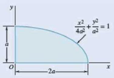
Fig. P9.67
(a)
Find the moment of inertia and product of inertia for quarter ellipse with respect new centroid axes obtained by rotating the x and y axes about O through
Answer to Problem 9.79P
The moment of inertia for quarter ellipse with respect to new centroid axes obtained by rotating the x about O through
The moment of inertia for quarter ellipse with respect to new centroid axes obtained by rotating the y about O through
The product of inertia for quarter ellipse with respect to new centroid axes obtained by rotating the x and y about O through
Explanation of Solution
Calculation:
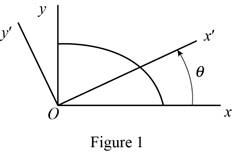
Sketch the quarter ellipse as shown in Figure 1.
Refer to Figure 9.12 “Moments of inertia of common geometric Shapes” in the textbook.
Find the moment of inertia
Here, a is moments and products of area for a quarter of a circle of radius.
Substitute
Find the moment of inertia
Substitute
Refer to problem 9.67.
Write the curve Equation as shown below:
Modify Equation (3).
Select a vertical strip as differential element of area.
Applying the parallel axis theorem.
Here,
Using the property of symmetry about x and y axis.
Express the variables in terms of x and y.
Find the coordinate of centroid element
Substitute
Consider the element strip as follows:
Integrating
Find the value of
Find the value of
Find the moment of inertia for quarter ellipse with respect new centroid axes obtained by rotating the x about O through
Refer to Equation 9.18 in section 9.3B in the textbook.
Substitute
Thus, the moment of inertia for quarter ellipse with respect new centroid axes obtained by rotating the x about O through
Find the moment of inertia for quarter ellipse with respect new centroid axes obtained by rotating the y about O through
Refer to Equation 9.19 in section 9.3B in the textbook.
Substitute
Thus, the moment of inertia for quarter ellipse with respect new centroid axes obtained by rotating the y about O through
Find the product of inertia for quarter ellipse with respect new centroid axes obtained by rotating the x and y about O through
Substitute
Thus, the product of inertia for quarter ellipse with respect new centroid axes obtained by rotating the x and y about O through
(b)
Find the moment of inertia and product of inertia with respect new centroid axes obtained by rotating the x and y axes about O through
Answer to Problem 9.79P
The moment of inertia for quarter ellipse with respect new centroid axes obtained by rotating the x about O through
The moment of inertia for quarter ellipse with respect new centroid axes obtained by rotating the y about O through
The product of inertia for quarter ellipse with respect new centroid axes obtained by rotating the x and y about O through
Explanation of Solution
Calculation:
Find the moment of inertia for quarter ellipse with respect new centroid axes obtained by rotating the x about O through
Refer to Equation 9.18 in section 9.3B in the textbook.
Substitute
Thus, the moment of inertia for quarter ellipse with respect new centroid axes obtained by rotating the x about O through
Find the moment of inertia for quarter ellipse with respect new centroid axes obtained by rotating the y about O through
Refer to Equation 9.19 in section 9.3B in the textbook.
Substitute
Thus, the moment of inertia for quarter ellipse with respect new centroid axes obtained by rotating the y about O through
Find the product of inertia for quarter ellipse with respect new centroid axes obtained by rotating the x and y about O through
Substitute
Thus, the product of inertia for quarter ellipse with respect new centroid axes obtained by rotating the x and y about O through
Want to see more full solutions like this?
Chapter 9 Solutions
VECTOR MECH...,STAT.+DYNA.(LL)-W/ACCESS
Additional Engineering Textbook Solutions
Thermodynamics: An Engineering Approach
Starting Out With Visual Basic (8th Edition)
Mechanics of Materials (10th Edition)
SURVEY OF OPERATING SYSTEMS
Database Concepts (8th Edition)
Electric Circuits. (11th Edition)


- Prob 2. The material distorts into the dashed position shown. Determine the average normal strains &x, Ey and the shear strain Yxy at A, and the average normal strain along line BE. 50 mm B 200 mm 15 mm 30 mm D ΕΙ 50 mm x A 150 mm Farrow_forwardProb 3. The triangular plate is fixed at its base, and its apex A is given a horizontal displacement of 5 mm. Determine the shear strain, Yxy, at A. Prob 4. The triangular plate is fixed at its base, and its apex A is given a horizontal displacement of 5 mm. Determine the average normal strain & along the x axis. Prob 5. The triangular plate is fixed at its base, and its apex A is given a horizontal displacement of 5 mm. Determine the average normal strain &x along the x' axis. x' 45° 800 mm 45° 45% 800 mm 5 mmarrow_forwardAn airplane lands on the straight runaway, originally travelling at 110 ft/s when s = 0. If it is subjected to the decelerations shown, determine the time t' needed to stop the plane and construct the s -t graph for the motion. draw a graph and show all work step by steparrow_forward
- dny dn-1y dn-1u dn-24 +a1 + + Any = bi +b₂- + +bnu. dtn dtn-1 dtn-1 dtn-2 a) Let be a root of the characteristic equation 1 sn+a1sn- + +an = : 0. Show that if u(t) = 0, the differential equation has the solution y(t) = e\t. b) Let к be a zero of the polynomial b(s) = b₁s-1+b2sn−2+ Show that if the input is u(t) equation that is identically zero. = .. +bn. ekt, then there is a solution to the differentialarrow_forwardB 60 ft WAB AB 30% : The crane's telescopic boom rotates with the angular velocity w = 0.06 rad/s and angular acceleration a = 0.07 rad/s². At the same instant, the boom is extending with a constant speed of 0.8 ft/s, measured relative to the boom. Determine the magnitude of the acceleration of point B at this instant.arrow_forwardThe motion of peg P is constrained by the lemniscate curved slot in OB and by the slotted arm OA. (Figure 1) If OA rotates counterclockwise with a constant angular velocity of 0 = 3 rad/s, determine the magnitude of the velocity of peg P at 0 = 30°. Express your answer to three significant figures and include the appropriate units. Determine the magnitude of the acceleration of peg P at 0 = 30°. Express your answer to three significant figures and include the appropriate units. 0 (4 cos 2 0)m² B Aarrow_forward
- 5: The structure shown was designed to support a30-kN load. It consists of a boom AB with a 30 x 50-mmrectangular cross section and a rod BC with a 20-mm-diametercircular cross section. The boom and the rod are connected bya pin at B and are supported by pins and brackets at A and C,respectively.1. Calculate the normal stress in boom AB and rod BC,indicate if in tension or compression.2. Calculate the shear stress of pins at A, B and C.3. Calculate the bearing stresses at A in member AB,and in the bracket.arrow_forward4: The boom AC is a 4-in. square steel tube with a wallthickness of 0.25 in. The boom is supported by the 0.5-in.-diameter pinat A, and the 0.375-in.-diameter cable BC. The working stresses are 25ksi for the cable, 18 ksi for the boom, and 13.6 ksi for shear in the pin.Neglect the weight of the boom.1. Calculate the maximum value of P (kips) based on boom compression and the maximum value of P (kips) based on tension in the cable.2. Calculate the maximum value of P (kips) based on shear in pin.arrow_forward3: A steel strut S serving as a brace for a boat hoist transmits a compressive force P = 54 kN to the deck of a pier as shown in Fig. STR-08. The strut has a hollow square cross section with a wall thickness t =12mm and the angle θ between the strut and the horizontal is 40°. A pin through the strut transmits the compressive force from the strut to two gusset plates G that are welded to the base plate B. Four anchor bolts fasten the base plate to the deck. The diameter of the pin is 20mm, the thickness of the gusset plates is 16mm, the thickness of the base plate is 8mm, and the diameter of the anchor bolts is 12mm. Disregard any friction between the base plate and the deck.1. Determine the shear stress in the pin, in MPa and the shear stress in the anchor bolts, in MPa.2. Determine the bearing stress in the strut holes, in MPa.arrow_forward
- 1. In the figure, the beam, W410x67, with 9 mm web thicknesssubjects the girder, W530x109 with 12 mm web thickness to a shear load,P (kN). 2L – 90 mm × 90 mm × 6 mm with bolts frame the beam to thegirder.Given: S1 = S2 = S5 = 40 mm; S3 = 75 mm; S4 = 110 mmAllowable Stresses are as follows:Bolt shear stress, Fv = 125 MPaBolt bearing stress, Fp = 510 MPa1. Determine the allowable load, P (kN), based on the shearcapacity of the 4 – 25 mm diameter bolts (4 – d1) and calculate the allowable load, P (kN), based on bolt bearing stress on the web of the beam.2. If P = 450 kN, determine the minimum diameter (mm) of 4 – d1based on allowable bolt shear stress and bearing stress of thebeam web.arrow_forward6: The 6-kN load P is supported by two wooden members of 75 x 125-mm uniform cross section that are joined by the simple glued scarf splice shown.1. Calculate the normal stress in the glue, in MPa.2. Calculate the shear stress in the glue, in MPa.arrow_forwardUsing Matlab calculate the following performance characteristics for a Tesla Model S undergoing the 4506 drive cycle test Prated Trated Ebat 80kW 254 Nm 85kWh/1645kg MUEH A rwheel 0.315M 133.3 C 0.491 Ng ng 7g 8.190.315 8.19 0.315 7ed= 85% Ebpt 35-956 DRIVE AXLE Ebfb chę =85% V Minverter H/A Battery Charger En AC Pry 9) required energy output from the motor to drive this cycle Cassume no regenerative braking) b) range of the Tesla Model S for this drive cycle (assume no regenerative breaking c) estimated mpge cycle of the Tesla Model S for this drive Cassume no regenerative breaking) d) Recalculate parts abc now assuming you can regenerate returns correctly due to inefficiency. from braking. Be careful to handle the diminishing energy braking makes in terms of required e) Quantify the percentage difference that regenerative required energy, range and mpge, DI L Ta a ra OLarrow_forward
 Elements Of ElectromagneticsMechanical EngineeringISBN:9780190698614Author:Sadiku, Matthew N. O.Publisher:Oxford University Press
 Mechanics of Materials (10th Edition)Mechanical EngineeringISBN:9780134319650Author:Russell C. HibbelerPublisher:PEARSON
 Thermodynamics: An Engineering ApproachMechanical EngineeringISBN:9781259822674Author:Yunus A. Cengel Dr., Michael A. BolesPublisher:McGraw-Hill Education
 Control Systems EngineeringMechanical EngineeringISBN:9781118170519Author:Norman S. NisePublisher:WILEY
 Mechanics of Materials (MindTap Course List)Mechanical EngineeringISBN:9781337093347Author:Barry J. Goodno, James M. GerePublisher:Cengage Learning
 Engineering Mechanics: StaticsMechanical EngineeringISBN:9781118807330Author:James L. Meriam, L. G. Kraige, J. N. BoltonPublisher:WILEY