
Videos
Find the moment and product of inertia of the area with respect to x and y axes about through
Answer to Problem 9.192RP
The moment of inertia of the area with respect to x about through
The moment of inertia of the area with respect to y about through
The product of inertia of the area with respect to x and y axes about through
Explanation of Solution
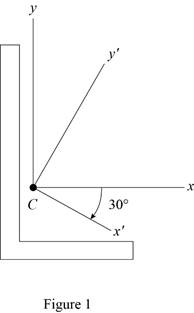
Sketch the cross section as shown in Figure 1.
Refer to Figure 9.13.
The moment of inertia
The moment of inertia
Refer to Problem 9.191.
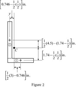
Sketch the cross section as shown in Figure 2.
Express the product of inertia as shown below:
Here,
Applying parallel axis theorem,
When the x and y axis is symmetry.
Refer to Figure 1.
Find the area of semicircle section 1 as shown below:
Here,
Substitute
Find the area of rectangle section 2 as shown below:
Here,
Substitute
Find the centroid for section 1 about x axis
Find the centroid for section 1 about x axis
Find the centroid for section 1 about y axis
Find the centroid for section 2 about x axis
Find the product of inertia of the area with respect to x and y axes by using parallel axis theorem as shown below:
Substitute
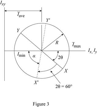
The Mohr circle is defined by the diameter XY, where
Find the average moment of inertia
Here,
Substitute
Find the radius (R) using the relation as shown below:
Here, R is radius and
Substitute
Sketch the Mohr circle as shown in Figure 3.
Refer to Figure 2.
Substitute
Find the angle
Find the moment of inertia of the area with respect to x about through
Here,
Substitute
Thus, the moment of inertia of the area with respect to x about through
Find the moment of inertia of the area with respect to y about through
Substitute
Thus, the moment of inertia of the area with respect to y about through
Find the product of inertia of the area with respect to y about through
Substitute
Thus, the product of inertia of the area with respect to x and y axes about through
(b)
Find the orientation of the principal axes through the centroid and corresponding values.
(b)
Answer to Problem 9.192RP
The orientation of the principal axes at the origin is
The maximum moment of inertia is
The minimum moment of inertia is
Explanation of Solution
Calculation:
Find the orientation of the principal axes through at origin as shown below.
Refer part a.
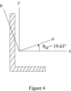
Thus, the orientation of the principal axes at the origin is
Sketch the orientation axis as shown in Figure 4.
Find the maximum moment
Substitute
Thus, the maximum moment of inertia is
Find the minimum moment
Substitute
Thus, the minimum moment of inertia is
Want to see more full solutions like this?
Chapter 9 Solutions
VECTOR MECH...,STAT.+DYNA.(LL)-W/ACCESS


- (read image) (answer given)arrow_forward11-5. Compute all the dimensional changes for the steel bar when subjected to the loads shown. The proportional limit of the steel is 230 MPa. 265 kN 100 mm 600 kN 25 mm thickness X Z 600 kN 450 mm E=207×103 MPa; μ= 0.25 265 kNarrow_forwardT₁ F Rd = 0.2 m md = 2 kg T₂ Tz1 Rc = 0.4 m mc = 5 kg m = 3 kgarrow_forward
- 2. Find a basis of solutions by the Frobenius method. Try to identify the series as expansions of known functions. (x + 2)²y" + (x + 2)y' - y = 0 ; Hint: Let: z = x+2arrow_forward1. Find a power series solution in powers of x. y" - y' + x²y = 0arrow_forward3. Find a basis of solutions by the Frobenius method. Try to identify the series as expansions of known functions. 8x2y" +10xy' + (x 1)y = 0 -arrow_forward
- Hello I was going over the solution for this probem and I'm a bit confused on the last part. Can you please explain to me 1^4 was used for the Co of the tubular cross section? Thank you!arrow_forwardBlood (HD = 0.45 in large diameter tubes) is forced through hollow fiber tubes that are 20 µm in diameter.Equating the volumetric flowrate expressions from (1) assuming marginal zone theory and (2) using an apparentviscosity for the blood, estimate the marginal zone thickness at this diameter. The viscosity of plasma is 1.2 cParrow_forwardQ2: Find the shear load on bolt A for the connection shown in Figure 2. Dimensions are in mm Fig. 2 24 0-0 0-0 A 180kN (10 Markarrow_forward
- determine the direction and magnitude of angular velocity ω3 of link CD in the four-bar linkage using the relative velocity graphical methodarrow_forwardFour-bar linkage mechanism, AB=40mm, BC=60mm, CD=70mm, AD=80mm, =60°, w1=10rad/s. Determine the direction and magnitude of w3 using relative motion graphical method. A B 2 3 77777 477777arrow_forwardFour-bar linkage mechanism, AB=40mm, BC=60mm, CD=70mm, AD=80mm, =60°, w1=10rad/s. Determine the direction and magnitude of w3 using relative motion graphical method. A B 2 3 77777 477777arrow_forward
 Elements Of ElectromagneticsMechanical EngineeringISBN:9780190698614Author:Sadiku, Matthew N. O.Publisher:Oxford University Press
 Mechanics of Materials (10th Edition)Mechanical EngineeringISBN:9780134319650Author:Russell C. HibbelerPublisher:PEARSON
 Thermodynamics: An Engineering ApproachMechanical EngineeringISBN:9781259822674Author:Yunus A. Cengel Dr., Michael A. BolesPublisher:McGraw-Hill Education
 Control Systems EngineeringMechanical EngineeringISBN:9781118170519Author:Norman S. NisePublisher:WILEY
 Mechanics of Materials (MindTap Course List)Mechanical EngineeringISBN:9781337093347Author:Barry J. Goodno, James M. GerePublisher:Cengage Learning
 Engineering Mechanics: StaticsMechanical EngineeringISBN:9781118807330Author:James L. Meriam, L. G. Kraige, J. N. BoltonPublisher:WILEY