
Concept explainers
Videos
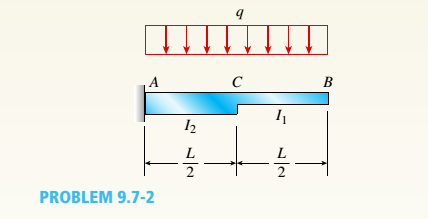
The cantilever beam ACB shown in the figure supports a uniform load of intensity q throughout its length. The beam has moments of inertia I2and IYin parts AC and CB, respectively.
- Using the method of superposition, determine the deflection SBat the free end due to the uniform load.
a.
The deflectiony13
Answer to Problem 9.7.2P
The deflectiony1313
Explanation of Solution
Given:
We have the data,
Length of the beam ACB as, L
Intensity of uniform load, q
Moment of inertia of,
Moment of inertia of,
Concept Used:
The cantilever beam ACB as per the below figure supports a uniform load of intensity q throughout its length with moments of inertia

Calculation:
We have the below diagram for part CB as below.
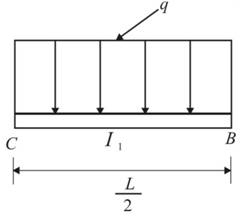
Deflection at point B would be calculated as,
We have the below diagram for part AC as below.
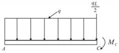
The moment at point C,
The deflection at point C can be calculated as below.
Angle of rotation at point C can be determined as,
At point B, the deflection would be,
Therefore, the total deflection at point B would be,
Conclusion:
The deflection
b.
The ratio r of the deflection
Answer to Problem 9.7.2P
The ratio r is
Explanation of Solution
Given:
We have the data,
Length of the beam, L
Moment of inertia of,
Moment of inertia of,
Load at point B, P
Concept Used:
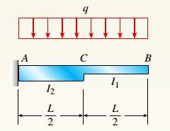
The cantilever beam ACB as per the below figure supports a uniform load of intensity q throughout its length with moments of inertia
Calculation:
For the prismatic cantilever beam, we have
We can calculate the ratio as below.
Conclusion:
The ratio r is calculated using the cantilever beam concept and moment diagram.
c.
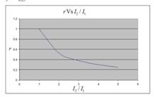
To plot : A graph for the deflection ratio (r) versus the ratio
Explanation of Solution
Given:
We have the data,
Length of the beam, L
Moment of inertia of,
Moment of inertia of,
Load at point B, P
Concept Used:
The cantilever beam ACB as per the below figure supports a uniform load of intensity q throughout its length with moments of inertia

Calculation:
The values for plotting graph are shown in below table:
| r | |
| 1 | 1 |
| 2 | 0.53 |
| 3 | 0.38 |
| 4 | 0.3 |
| 5 | 0.25 |
We will get graph as shown below:

Conclusion:
The graph for the deflection ratio (r) versus the ratio
Want to see more full solutions like this?
Chapter 9 Solutions
Mechanics of Materials, SI Edition


- Please also draw the FBDsarrow_forwardDesign Description: Fresh water tank, immersed in an oil tank.a) Water tank:a. Shape: Cylindricalb. Radius: 1 meterc. Height: 3 metersd. Bottom airlock: 0.2m x 0.2m. b) Oil tank:a. Shape: cylindricalb. Radius: 4 metersc. Oil density: 850 kg/m³ Determine:a) The pressure experienced by an airlock at the bottom of the tank with water.b) The force and direction necessary to open the lock, suppose the lock weighs 20 Newtons, suppose the lock opens outwards. The image is for illustrative purposes, the immersed cylinder does not reach the bottomarrow_forwardNeed help!arrow_forward
- need help understanding?arrow_forward%94 KB/S Find : 1. dynamic load on each bearing due to the out-of-balance couple; and 2. kinetic energy of the complete assembly. [Ans. 6.12 kg: 8.7 N-m] L 2. 3. 4. 5. 1. 2. 5. DO YOU KNOW? Why is balancing of rotating parts necessary for high speed engines? Explain clearly the terms "static balancing' and 'dynamic balancing'. State the necessary conditions to achieve them. Discuss how a single revolving mass is balanced by two masses revolving in different planes. Chapter 21: Balancing of Rotating Masses .857 Explain the method of balancing of different masses revolving in the same plane. How the different masses rotating in different planes are balanced? OBJECTIVE TYPE QUESTIONS The balancing of rotating and reciprocating parts of an engine is necessary when it runs at (a) slow speed (b) medium speed (c) high speed A disturbing mass, attached to a rotating shaft may be balanced by a single mass m, attached in the same plane of rotation as that of my such that (a) (b) F For static…arrow_forwardProvide a real-world usage example of the following: Straightness Circularity Parallelism What specific tools, jigs, and other devices are used to control the examples you provided?arrow_forward
- 856 Theory of Machines 5. A shaft carries five masses A, B, C, D and E which revolve at the same radius in planes which are equidistant from one another. The magnitude of the masses in planes A, C and D are 50 kg, 40 kg and 80 kg respectively. The angle between A and C is 90° and that between C and D is 135° Determine the magnitude of the masses in planes B and E and their positions to put the shaft in complete rotating balance. [Ans. 12 kg, 15 kg; 130° and 24° from mass A in anticlockwise direction]arrow_forward2. 3. 4. clockwise from Four masses A, B, C and D revolve at equal radii and are equally spaced along a shaft. The mass B is 7 kg and the radii of C and D make angles of 90° and 240° respectively with the radius of B. Find the magnitude of the masses A, C and D and the angular position of A so that the system may be completely balanced. [Ans. 5 kg: 6 kg; 4.67 kg; 205° from mass B in anticlockwise direction] A rotating shaft carries four masses A, B, C and D which are radially attached to it. The mass centres are 30 mm, 38 mm, 40 mm and 35 mm respectively from the axis of rotation. The masses A, C and D are 7.5 kg. 5 kg and 4 kg respectively. The axial distances between the planes of rotation of A and B is 400 mm and between B and C is 500 mm. The masses A and C are at right angles to each other. Find for a complete balance, 1. the angles between the masses B and D from mass A, 2. the axial distance between the planes of rotation of C and D. 3. the magnitude of mass B. [Ans. 162.5%,…arrow_forward1. Four masses A, B, C and D are attached to a shaft and revolve in the same plane. The masses are 12 kg. 10 kg. 18 kg and 15 kg respectively and their radii of rotations are 40 mm, 50 mm, 60 mm and 30 mm. The angular position of the masses B, C and D are 60°, 135° and 270 from the mass A. Find the magnitude and position of the balancing mass at a radius of 100 mm. [Ans. 7.56 kg: 87 clockwise from A]arrow_forward
- 3. The structure in Figure 3 is loaded by a horizontal force P = 2.4 kN at C. The roller at E is frictionless. Find the axial force N, the shear force V and the bending moment M at a section just above the pin B in the member ABC and illustrate their directions on a sketch of the segment AB. B P D A 65° 65° E all dimensions in meters Figure 3arrow_forward4. The distributed load in Figure 4 varies linearly from 3wo per unit length at A to wo per unit length at B and the beam is built in at A. Find expressions for the shear force V and the bending moment M as functions of x. 3W0 Wo A L Figure 4 2 Barrow_forward1. The beam AB in Figure 1 is subjected to a uniformly distributed load wo = 100 N/m. Find the axial force N, the shear force V and the bending moment M at the point D which is midway between A and B and illustrate their directions on a sketch of the segment DB. wo per unit length A D' B all dimensions in metersarrow_forward
 Mechanics of Materials (MindTap Course List)Mechanical EngineeringISBN:9781337093347Author:Barry J. Goodno, James M. GerePublisher:Cengage Learning