Principles of Foundation Engineering (MindTap Course List)
8th Edition
ISBN: 9781305081550
Author: Braja M. Das
Publisher: Cengage Learning
expand_more
expand_more
format_list_bulleted
Textbook Question
Chapter 9, Problem 9.4P
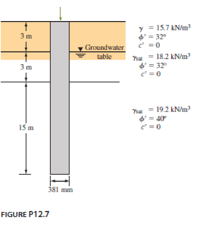
A driven closed-ended pile, circular in cross section, is shown in Figure P12.7. Calculate the following.
- a. The ultimate point load using Meyerhof’s procedure.
- b. The ultimate point load using Vesic’s procedure. Take Irr = 50.
- c. An approximate ultimate point load on the basis of parts (a) and (b).
- d. The ultimate frictional resistance Qs. [Use Eqs. (12.42) through (12.44), and take K = 1.4 and δ′ = 0.6ϕ′.]
- e. The allowable load of the pile (use FS = 4).

Expert Solution & Answer
Trending nowThis is a popular solution!

Students have asked these similar questions
(A): As shown in the rig. A hydraulic jump was occurred in a rectangular channel,the velocity
of flow before and after the jump equal to 8 m/s and 2 m/s respectively.
Find: The energy dissipation for the jump (AE) and what is the name of this jump.
V1-8 m/s
-V2-2 m/s
A cylinder of fluid has dimensions of 0.2 ft in diameter by 0.45 ft high. If the weight of thefluid is 0.55 lb , determine the specific gravity and density of fluid.
A cylinder of fluid has dimensions of 0.2 ft in diameter by 0.45 ft high. If the weight of thefluid is 0.55 lb , determine the specific gravity and density of fluid.
Chapter 9 Solutions
Principles of Foundation Engineering (MindTap Course List)
Ch. 9 - A 20 m long concrete pile is shown in Figure...Ch. 9 - Refer to the pile shown in Figure P9.1. Estimate...Ch. 9 - Prob. 9.3PCh. 9 - A driven closed-ended pile, circular in cross...Ch. 9 - Prob. 9.5PCh. 9 - Prob. 9.6PCh. 9 - Prob. 9.7PCh. 9 - Prob. 9.8PCh. 9 - Prob. 9.9PCh. 9 - A concrete pile 16 in. 16 in. in cross section is...
Ch. 9 - Prob. 9.11PCh. 9 - Solve Problem 12.13 using Eqs. (12.59) and...Ch. 9 - Prob. 9.13PCh. 9 - Prob. 9.14PCh. 9 - A steel pile (H-section; HP 310 125; see Table...Ch. 9 - A concrete pile is 20 m long and has a cross...Ch. 9 - Prob. 9.17PCh. 9 - Prob. 9.18PCh. 9 - Solve Problem 12.23 using the method of Broms....Ch. 9 - Prob. 9.20PCh. 9 - Solve Problem 12.25 using the modified EN formula....Ch. 9 - Solve Problem 12.25 using the modified Danish...Ch. 9 - Figure 12.49a shows a pile. Let L = 15 m, D (pile...Ch. 9 - Redo Problem 12.30 assuming that the water table...Ch. 9 - Refer to Figure 12.49b. Let L = 18 m, fill = 17...Ch. 9 - A concrete pile measuring 16 in. × 16 in. in cross...Ch. 9 - The plan of a group pile is shown in Figure...Ch. 9 - Prob. 9.28PCh. 9 - The section of a 4 × 4 group pile in a layered...Ch. 9 - Prob. 9.30P
Knowledge Booster
Learn more about
Need a deep-dive on the concept behind this application? Look no further. Learn more about this topic, civil-engineering and related others by exploring similar questions and additional content below.Similar questions
- A cylinder of fluid has dimensions of 0.2 ft in diameter by 0.45 ft high. If the weight of thefluid is 0.55 lb , determine the specific gravity and density of fluid.arrow_forwardDraw the shear and bending moment diagrams and find the immediate deflection for a simply supported beam of length 20 ft. with the same live load at ½ span and cross-section as the previous problem. Assume a reasonable Modulus of Elasticity and concrete self-weight. Hint: You may look online for typical concrete self-weights and compressive strengths. You may also use the ACI 318 Code equation for the Modulus of Elasticity shown below, and the supplied Design Aids.arrow_forwardProblem 4. A major transmission pathway of the novel coronavirus disease 2019 (COVID- 19) is through droplets and aerosols produced by violent respiratory events such as sneezes and coughs (Fig. 1). For the purpose of providing public health guidelines, we would like to estimate the amount of time it takes for these droplets to settle from air to the ground. The relevant parameters are the settling time (ts), the initial height of the droplets (H), gravitational acceleration (g), density of the droplets (pa), radius of the droplets (R), as well as dynamic viscosity of the ambient air (Pair). Use dimensional analysis and the Buckingham theorem to answer the following questions: 1. Find the independent dimensionless parameters using the table method. Then, express the settling time as a function of the other relevant parameters. Your solution should match the physical intuition that the settling time scales linearly with the initial height. 2. How would the settling change if the…arrow_forward
- Question 4 An engineer is assigned to design a 25-stories office building which has a building height of 75 m. Reinforced concrete shear wall system as shown in Figure Q1(a) is adopted to resist the lateral loads. The shear wall is of thickness t = 350 mm and length L = 8.5 m. Use the following data: Young's modulus of concrete E = 28 kN/mm² and the lateral load intensity w = 1.20 kN/m². Assuming the frontal width of the building façade is 15 m is facing the wind force which in turn transmitting the wind force to the shear wall system, estimate the total value of sway A at the roof level. Question 5 For the Shear Wall in Question 4, if the total ultimate gravity load of the building acted on shear wall is 6000 KN, using a partial factor of 1.2 for the wind load, calculate the stress on the extreme right corner of the shear wall at first storey level. (A) 9.46 mm (B) 189.26 mm (C) 14.20 mm (D) 141.95 mm STOREY FLOOR LEV Shear wall Figure Q1(a) (A) 3.228 N/sq mm (B) 14.029 N/sq mm 75 m…arrow_forwardQuestion 4 An engineer is assigned to design a 25-stories office building which has a building height of 75 m. Reinforced concrete shear wall system as shown in Figure Q1(a) is adopted to resist the lateral loads. The shear wall is of thickness t = 350 mm and length L = 8.5 m. Use the following data: Young's modulus of concrete E = 28 kN/mm² and the lateral load intensity w = 1.20 kN/m². Assuming the frontal width of the building façade is 15 m is facing the wind force which in turn transmitting the wind force to the shear wall system, estimate the total value of sway A at the roof level. Question 6 If the similar building in Question 4 is designed using rigid frame method is to be designed to ensure the sway is within the allowable limit. If the building width is B, and with the same building height H=75m. Using a rough estimation method, calculate the maximum allowable deflection A at the roof level. (A) 9.46 mm (B) 189.26 mm (C) 14.20 mm 町 141.95 mm 1ST STOREY FLOOR LEV. Shear wall…arrow_forwardWhat are the biggest challenges estimators' face during the quantity takeoff and pricing phases?arrow_forward
- Question IV (30%): A 22 m thick normally consolidated clay layer has a load of 150 kPa applied to it over a large areal extent. The clay layer is located below a 3.5 m thick granular fill (p= 1.8 Mg/m³). A dense sandy gravel is found below the clay. The groundwater table is located at the top of the clay layer, and the submerged density of the clay soil is 0.95 Mg/m³. Consolidation tests performed on 2.20 cm thick doubly drained samples indicate the time for 50% consolidation completed as t50 = 10.5 min for a load increment close to that of the loaded clay layer. Compute the effective stress in the clay layer at a depth of 16 m below the ground surface 3.5 years after the application of the load.arrow_forward13-3. Use the moment-distribution method to determine the moment at each joint of the symmetric bridge frame. Supports at F and E are fixed and B and C are fixed connected. Use Table 13-2. The modulus of elasticity is constant and the members are each 0.25 m thick. The haunches are parabolic. *13-4. Solve Prob. 13-3 using the slope-deflection equations. 13 0.5 m 1 m 64 kN/m D BC 1.5 m 2.25 m 2 m 6.25 m -0.5 m E -7.5 m -10 m- -7.5 m. Probs. 13-3/4arrow_forward2. Find the equivalent concentrated load(s) for the bags of cement stacked on the dock as shown here. Each bag weighs 100 lbs and is 12 inches long. Draw the loading conditions for each showing the equivalent concentrated load(s). 1 bag = 100lbs L= 12 ft L= 6 ft L= 8ftarrow_forward
- I have a question for this problem in the first one wouldn't it be finding the total weight of the bags which =4800lbs and the multiply that by 12ft to find the concentrated load?? but if this is the case the load would end up as lbs/ft so I'm not too sure that is right.arrow_forwardThere are 2 parts A) L=12ft B) L1= 6ft, L2= 8ftarrow_forwardto determine the bearing capacity for the given beam a=0.5 m sigma1 =150 N/mm2 and sigma2 =200N/mm2.arrow_forward
arrow_back_ios
SEE MORE QUESTIONS
arrow_forward_ios
Recommended textbooks for you
 Principles of Foundation Engineering (MindTap Cou...Civil EngineeringISBN:9781337705028Author:Braja M. Das, Nagaratnam SivakuganPublisher:Cengage Learning
 Fundamentals of Geotechnical Engineering (MindTap...Civil EngineeringISBN:9781305635180Author:Braja M. Das, Nagaratnam SivakuganPublisher:Cengage Learning
 Principles of Foundation Engineering (MindTap Cou...Civil EngineeringISBN:9781305081550Author:Braja M. DasPublisher:Cengage Learning
 Principles of Geotechnical Engineering (MindTap C...Civil EngineeringISBN:9781305970939Author:Braja M. Das, Khaled SobhanPublisher:Cengage Learning

Principles of Foundation Engineering (MindTap Cou...
Civil Engineering
ISBN:9781337705028
Author:Braja M. Das, Nagaratnam Sivakugan
Publisher:Cengage Learning

Fundamentals of Geotechnical Engineering (MindTap...
Civil Engineering
ISBN:9781305635180
Author:Braja M. Das, Nagaratnam Sivakugan
Publisher:Cengage Learning

Principles of Foundation Engineering (MindTap Cou...
Civil Engineering
ISBN:9781305081550
Author:Braja M. Das
Publisher:Cengage Learning

Principles of Geotechnical Engineering (MindTap C...
Civil Engineering
ISBN:9781305970939
Author:Braja M. Das, Khaled Sobhan
Publisher:Cengage Learning
Concrete Slab Calculations 006; Author: Jerry Howard;https://www.youtube.com/watch?v=R19jILyBxio;License: Standard Youtube License