
Videos
(a)
To compute:
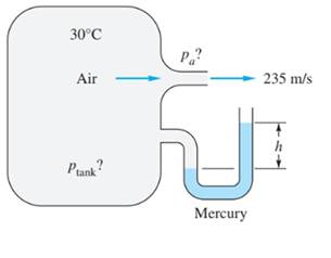
The pressure in the tank.
Answer to Problem 9.32P
Explanation of Solution
Given information:
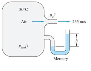
The nozzle exit velocity is equal to
The stagnation temperature is defined as,
Where,
Speed of sound is defined as,
Where,
The Mach number is defined as,
Where,
The pressure ratio is defined as,
Where,
Calculation:
Convert,
Calculate the exit temperature,
Substitute for known values,
Therefore,
Calculate the Mach number at exit,
Calculate the pressure ratio,
In above equation,
Therefore,
Apply hydrostatic formula for above system,
Assume, the specific weight of mercury as,
Therefore,
According to equation 1 and 2,
The pressure inside the tank is equal to,
Conclusion:
The pressure inside the tank is equal to,
(b)
The atmospheric pressure.
Answer to Problem 9.32P
Explanation of Solution
Given information:

The nozzle exit velocity is equal to
The stagnation temperature is defined as,
Where,
Speed of sound is defined as,
Where,
The Mach number is defined as,
Where,
The pressure ratio is defined as,
Where,
Calculation:
Convert,
Calculate the exit temperature,
Substitute for known values,
Therefore,
Calculate the Mach number at exit,
Calculate the pressure ratio,
In the above equation,
Therefore,
Apply hydrostatic formula for the above system,
Assume, the specific weight of mercury as,
Therefore,
According to equation 1 and 2,
The atmospheric pressure is equal to,
Conclusion:
The atmospheric pressure is equal to,
(c)
To calculate:
The Mach number at exit.
Answer to Problem 9.32P
Explanation of Solution
Given information:
The nozzle exit velocity is equal to
The stagnation temperature is defined as,
Where,
Speed of sound is defined as,
Where,
The Mach number is defined as,
Where,
Calculation:
Convert,
Calculate the exit temperature,
Substitute for known values,
Therefore,
Calculate the Mach number at exit,
Conclusion:
The Mach number at exit is equal to
Want to see more full solutions like this?
Chapter 9 Solutions
Fluid Mechanics, 8 Ed


- The 2nd Law of Thermodynamics A 3.5-m3 rigid tank initially contains air whose density is 2 kg/m3. The tank is connected to a high-pressuresupply line through a valve. The valve is opened, and air is allowed to enter the tank until the density in thetank rises to 6.5 kg/m3. Determine the mass of air that has entered the tank.arrow_forwardTELEGRAM 426 LTE 11. 5:59 Dynamic تم Dynamic Fluids with Applications@le... H.W Q2: The oil tank for a hydraulic system (shown in Fig. 6.5) has the following details: (a) The oil tank is air pressurized at 68.97 kPa gauge pressure. (b) The inlet to the pump is 3.048 m below the oil level. (c) The pump flow rate is 0.001896 m3/s. (d) The specific gravity of oil is 0.9. (e) The kinematic viscosity of oil is 100 cS. (f) Assume that the pressure drop across the strainer is 6.897 kPa. (g) The pipe diameter is 38.1 mm. (h) The total length of the pipe is 6.097 m. Find the pressure at station 2. by Dr. Ali Khaleel Kareem H.W by Dr. Ali Khaleel Kareem Breather Three standard elbows (A, B and C) 3 m Pump Figure 6.5 38 mm (ID) Pipe length = 6m 20 21arrow_forwardA 3 m x 5 m section of wall of the cold room is not insulated, and the temperature at the outer surface of this section is measured to be 7°C. The temperature of the outside room is 30°C, and the combined convection and radiation heat transfer coefficient at the surface of the outer wall is 10 W/m2°C. It is proposed to insulate this section of the furnace wall with glass wool insulation (k = 0.038 W/m°C) in order to reduce the heat transfer by 90%. Assuming the outer surface temperature of the cold room wall section still remains at about 7°C, determine the thickness of the insulation that needs to be used. The company is questioning whether to insulate the section of piping between the evaporator and the compressor. Present (using equations to support your reasoning) whether you would support this idea or notarrow_forward
- Q1.Given the unity feedback system with a forward path transfer function, G(s) = = K (s+1)(s+2)(s+6) . Do the following: (a) Draw the root locus (b) Find the gain, K, and natural frequency for a damping ratio 0.5. (c) Find the range or value of gain, K for i. overdamped ii. critically damped iii. Undamped iv. underdampedarrow_forwardQ. 1: The partial Routh array of a unity feedback system is given below. S6 1 Adel 8 S5 1 S4 2 Bash 6 -4 0 C 0 How many roots does it have in the right half plane? Comment on the stability of the system. Determine the characteristic equation of the system. Q.2: Find the values of Ki and K2 for the system shown in the figure below when Mp=0.25% and tp= 4 sec. assume unit step input. R(S) K₁ C(S) 1+ K₂Sarrow_forwardTemperature EXAMPLE 1: A diesel engine is fitted with a turbocharger, which comprises a radial compressor driven by a radial exhaust gas turbine. The air is drawn into the compressor at a pressure of 0.95 bar and at a temperature of 15°C, and is delivered to the engine at a pressure of 2.0 bar. The engine is operating on a gravimetric air/fuel ratio of 18: 1, and the exhaust leaves the engine at a temperature of 600°C and at a pressure of 1.8 bar; the turbine exhausts at 1.05 bar. The isentropic efficiencies of the compressor and T(K) turbine are 70 per cent and 80 per cent, respectively. Calculate (i) the temperature of the air leaving the compressor (ii) the temperature of the gases leaving the turbine (iii) the mechanical power loss in the turbocharger expressed as a percentage of the power generated in the turbine. Using the values of : Cpair = 1.01 kJ/kg K, Vair = 1.4 Cpex = 1.15 kJ/kg K, Yex = 1.33 and 2s с P2 Engine P3 W W₁ = mexpex (T3-TA) At W₁ = mair Cpex (T2-T₁) 4 P4…arrow_forward
- Problem 8.28 Part A 10 of 10 ■Review The uniform crate resting on the dolly has a mass of 530 kg and mass center at G as shown in (Figure 1). If the front casters contact a high step, and the coefficient of static friction between the crate and the dolly is μs = 0.45, determine the greatest force P that can be applied without causing motion of the crate. The dolly does not move. Express your answer to three significant figures and include the appropriate units. Figure -0.5 m- 0.6 m 0.3 m 0.1 m B 0.4 m 0.3 m > ☐ P = 1210 Submit о ΜΑ N Previous Answers Request Answer × Incorrect; Try Again 1 of 1 < Return to Assignment Provide Feedback ?arrow_forwardQ1: For the system shown in Fig. 6.7, the following data are applicable P1 = 7 bar Q=0.002 m3/sec Pipe: total length 15m and ID 38mm Oil: SG-0.90 and kinematic viscosity (v-0.0001 m2/s) Solve for P2 in units of bars. Motor OH Pump Breather P1 Pipe length = 3m 90' elbow ☐ 38 mm (ID) Pipe length = 2m P2 Load force Pipe length 4 m = Pipe length=6m 90' elbowarrow_forwardusing the three moment theorem please find the moments about B, C and Darrow_forward
- A viscous fluid flows in a 0.10-m-diameter pipe such that its velocity measured 0.010 m away from the pipe wall is 0.9 m/s. If the flow is laminar, determine (a) the centerline velocity and (b) the flowrate. (a) Vi (b) Q = i m/s × 103 m³/sarrow_forwardThis is an old exam review question please help.arrow_forwardThis is an old exam review problem. Please helparrow_forward
 Elements Of ElectromagneticsMechanical EngineeringISBN:9780190698614Author:Sadiku, Matthew N. O.Publisher:Oxford University Press
 Mechanics of Materials (10th Edition)Mechanical EngineeringISBN:9780134319650Author:Russell C. HibbelerPublisher:PEARSON
 Thermodynamics: An Engineering ApproachMechanical EngineeringISBN:9781259822674Author:Yunus A. Cengel Dr., Michael A. BolesPublisher:McGraw-Hill Education
 Control Systems EngineeringMechanical EngineeringISBN:9781118170519Author:Norman S. NisePublisher:WILEY
 Mechanics of Materials (MindTap Course List)Mechanical EngineeringISBN:9781337093347Author:Barry J. Goodno, James M. GerePublisher:Cengage Learning
 Engineering Mechanics: StaticsMechanical EngineeringISBN:9781118807330Author:James L. Meriam, L. G. Kraige, J. N. BoltonPublisher:WILEY