
Concept explainers
Videos
The expression for the steady state voltage vo (t)for a full wave rectifier.
The steady stat response for the given fullwave rectifier is given by,

Given: The sinusoidal voltage waveform of a fullwave rectifier
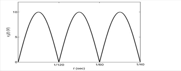
FigureP9.31
Fourier series approximation and is given by
Fourier series approximation = vs (t) = 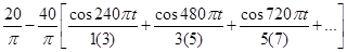
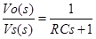
Transfer function =  Where R = 600
  and C
and C 
Concept Used:
We first calculate  magnitude of the given transfer function, phase angle, bandwidth and magnitude of phase angles of respective frequencies and finally calculate the expression for steady state response of the full wave rectifier.
Calculation:
The Fourier series approximation is given by,
vs (t) = 
The transfer function of series RC circuit is given by,
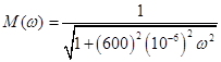
The expression for magnitude of transfer function of the given full wave rectifier is
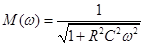 (1)
(1)
Substituting for R = 600  and C
and C  in equation (1) we get,
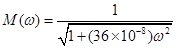 (2)
(2)
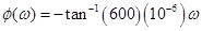
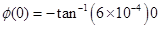
The phase angle for the given fullwave rectifier is given by
 .... (3)
Substituting for R = 600  and C
and C  in equation (3) we get,
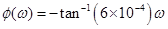 .... (4)
The bandwidth  for the given system should lie between 0 and

 (5)
(5)
Substituting for R = 600  and C
and C  in equation (5) we get,

 1666.67 rad/s
As  is greater than 1666.67 rad/s which is outside the required bandwidth, we consider only 0, 240
  and 480
  only for frequency values.
The magnitude value for the frequencies 0, 240  and 480
  is,
is,
From equation (2) we know that

Substituting for  0, 240
  and 480
  respectively we get
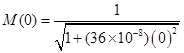
 (6)
(6)
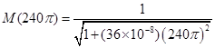
On simplifying we get
 0.9111.... (7)
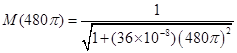
On simplifying we get
 (8)
(8)
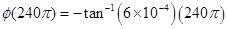
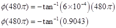
From equation (4) we have 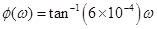
Now calculating the phase angles for corresponding frequencies 0, 240  and 480
  respectively we get,


The steady state voltage for the given full-wave rectifier with Fourier series,
vs (t  is given by


Conclusion:
Therefore, the steady state response for the given fullwave rectifier is given by,

Want to see the full answer?
Check out a sample textbook solution
Chapter 9 Solutions
EBK SYSTEM DYNAMICS


- H.W 4: The beam shown below is subjected to the distributed loading of w=120 kN/m. Determine the principal stresses in the beam at point P, which lies at the top of the web. Neglect the size of the fillets and stress concentrations at this point. I=67.4×10⁻⁶ m4. 15 mm w=120 kN/m B 0.3 m 2 200 mm A 10 rim 15 mm 175 mmarrow_forwardA 3 m x 5 m section of wall of the cold room is not insulated, and the temperature at the outer surface of this section is measured to be 7°C. The temperature of the outside room is 30°C, and the combined convection and radiation heat transfer coefficient at the surface of the outer wall is 10 W/m2°C. It is proposed to insulate this section of the furnace wall with glass wool insulation (k = 0.038 W/m°C) in order to reduce the heat transfer by 90%. Assuming the outer surface temperature of the cold room wall section still remains at about 7°C, determine the thickness of the insulation that needs to be used.arrow_forwardQ1/ For what value of x do the power series converge: ∞ Σ(-1)-1 n=1 x2n-1 2n-1 =x x3 3 5 Q2/ Find the Interval of convergence and Radius of convergence of the series : Σ n=1 n 3n+1 (x)" الممسوحة ضوئيا بـ CS CamScannerarrow_forward
- This refrigeration cycle uses R-134a as the working fluid and, for now, assume that it operates on an ideal vapour-compression refrigeration cycle between 0.11 and 1.0 MPa. If the mass flow rate of the refrigerant is 0.075 kg/s, determine What is the rate of heat removal from the refrigerated space? What is the power input to the compressor? What is the rate of heat rejection to the environment? What is the COP of this ideal process? Based on this analysis, what is the cost of electricity to operate the cold room for 1 year? Comment on why this differs to the value above Further data was collected which determined that the working fluid: enters the compressor at 0.11 MPa and -22°C leaves the compressor at 1.0 MPa and 60°C is cooled in the condenser to 0.9 MPa and 20°C is throttled to 0.12 MPa Disregarding any heat transfer or pressure losses in the pipes: What is the rate of heat removal from the refrigerated space? What is the power input to the compressor?…arrow_forward1 The refrigeration capacity of the cold room you are considering is 10 kW. It operates for 24 h/d, 360 days of the year. The average temperature outside the cold room is 30°C and the temperature of the air inside the cold room should be 5°C. What is the maximum coefficient of performance for this refrigeration cycle? What is the minimum work required? and If the price of electricity is 0.008 cents per kJ, what is the minimum cost of electricity to run the cold room for 1 year?arrow_forwardThis refrigeration cycle uses R-134a as the working fluid and, for now, assume that it operates on an ideal vapour-compression refrigeration cycle between 0.11 and 1.0 MPa. If the mass flow rate of the refrigerant is 0.075 kg/s, determine What is the rate of heat removal from the refrigerated space? What is the power input to the compressor? What is the rate of heat rejection to the environment? and What is the COP of this ideal process?arrow_forward
 Elements Of ElectromagneticsMechanical EngineeringISBN:9780190698614Author:Sadiku, Matthew N. O.Publisher:Oxford University Press
 Mechanics of Materials (10th Edition)Mechanical EngineeringISBN:9780134319650Author:Russell C. HibbelerPublisher:PEARSON
 Thermodynamics: An Engineering ApproachMechanical EngineeringISBN:9781259822674Author:Yunus A. Cengel Dr., Michael A. BolesPublisher:McGraw-Hill Education
 Control Systems EngineeringMechanical EngineeringISBN:9781118170519Author:Norman S. NisePublisher:WILEY
 Mechanics of Materials (MindTap Course List)Mechanical EngineeringISBN:9781337093347Author:Barry J. Goodno, James M. GerePublisher:Cengage Learning
 Engineering Mechanics: StaticsMechanical EngineeringISBN:9781118807330Author:James L. Meriam, L. G. Kraige, J. N. BoltonPublisher:WILEY