
Concept explainers
Videos
Consider the oneline diagram of a simple power system shown in Figure 9.20. System data in per-unit on a 100-MVA base are given as follows:
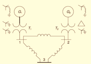
The neutral of each generator is grounded through a current-limiting reactor of 0.08333 per unit on a 100-MVA base. All transformer neutrals are solidly grounded. The generators are operating no-load at their rated voltages and rated frequency with their ENIFs in phase. Determine the fault current for a balanced three-phase fault at bus 3 through a fault impedance

Trending nowThis is a popular solution!

Chapter 9 Solutions
Power System Analysis and Design (MindTap Course List)


- For the circuit shown in Fig. 2.18, he =1.1 K2, hfe =50. Find Avf, Rif and Rof. { Ans: -3.2; 1935; X2807. Ans:-3-2;193;728. Vcc Rs=10kQ RF = 40kQ Re=4KQ -ov Vs Fig. 2.18 Circuit for Q5.arrow_forwardThe circuit of Fig. 2.16 is to have Af=-1mA/V, D=1+ BA = 50, a voltage gain of -4, Rs =1KQ, and hfe = 150. Find RL, Re, Rif and Rof.. Vcc www RL OV Ans: 4 kor; 98053150 KS;∞. { An Re Fig. 2.16 Circuit for Q3.arrow_forwardDuring the lab you will design and measure a differential amplifier, made with an opamp. inside generator R5 ww 500 V1 0.1Vpk 1kHz 0° R6 w 50Ω R1 ww 10ΚΩ VCC C1 balanced wire R3 w 15.0V signal+ 100nF U1A TL082CP ground 2 signal- R4 w C2 Question5: Calculate R3 and R4 for a 20dB. 100nF VEE -15.0V R2 ww 10ΚΩarrow_forward
- not use ai pleasearrow_forward3. Consider the system described by the transfer function Gp(s) polynomial controller to satisfy the below specifications: 1) The settling time is t = 1 second, 2) 0.1% peak overshoot, 3) and zero steady-state error for a ramp input. The sampling period is T = 0.01 second. 1 = Design a discrete-time s(s+5)*arrow_forwardProblem 2 Does there exist a value a that makes the two systems S₁ and S₂ equal? If so, what is this value ? If not, explain why. S₁ x[n] x[n] D D -2 → host 回洄 S with h[m] " 999. усиз -1012345 harrow_forward
- please not use any aiarrow_forwardProblem 2 Does there exist a value a that makes the two systems S₁ and S₂ equal? If so, what is this value ? If not, explain why. S₁ x[n] x[n] D D -2 → host 回洄 S with h[m] " 999. усиз -1012345 harrow_forwardSolve only no 8, Don't use chatgpt or any , only expertarrow_forward
- I need help in creating a matlab code to find the currents USING MARTIXS AND INVERSE to find the currentarrow_forwardQuestion 2 A transistor is used as a switch and the waveforms are shown in Figure 2. The parameters are Vcc = 225 V, VBE(sat) = 3 V, IB = 8 A, VCE(sat) = 2 V, Ics = 90 A, td = 0.5 µs, tr = 1 µs, ts = 3 µs, tƒ = 2 μs, and f 10 kHz. The duty cycle is k 50%. The collector- emitter leakage current is ICEO = 2 mA. Determine the power loss due to the collector current: = = = (a) during turn-on ton = td + tr VCE Vcc (b) during conduction period tn V CE(sat) 0 toff" ton Ics 0.9 Ics (c) during turn-off toff = ts + tf (d) during off-time tot (e) the total average power losses PT ICEO 0 IBS 0 Figure 2 V BE(sat) 0 主 * td tr In Is If to iB VBE T= 1/fsarrow_forwardQuestion 1: The beta (B) of the bipolar transistor shown in Figure 1 varies from 12 to 60. The load resistance is Rc = 5. The dc supply voltage is VCC = 40 V and the input voltage to the base circuit is VB = 5 V. If VCE(sat) = 1.2 V, VBE(sat) = 1.6 V, and RB = 0.8 2, calculate: (a) the overdrive factor ODF. (b) the forced ẞ (c) the power loss in the transistor PT. IB VB RB + V BE RC Vcc' Ic + IE Figure 1 VCEarrow_forward
 Power System Analysis and Design (MindTap Course ...Electrical EngineeringISBN:9781305632134Author:J. Duncan Glover, Thomas Overbye, Mulukutla S. SarmaPublisher:Cengage Learning
 EBK ELECTRICAL WIRING RESIDENTIALElectrical EngineeringISBN:9781337516549Author:SimmonsPublisher:CENGAGE LEARNING - CONSIGNMENT