(a)
Interpretation:
The circulation rate of refrigerant for the given system is to be calculated.
Concept introduction:
Below shown diagram represents vapor-compression refrigeration cycle on a
The line
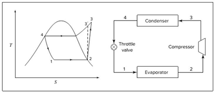
The equations used to calculate the heat absorbed in evaporator and the heat rejected in condenser are:
The work of compression is:
The coefficient of performance is:
The rate of circulation of refrigerant,
For Carnot refrigeration cycle, highest possible value of
(b)
Interpretation:
The reduction in the circulation rate is to be calculated if throttle valve is replaced by a turbine where the refrigerant expands isentropically.
Concept introduction:
Below shown diagram represents vapor-compression refrigeration cycle on a
The line

The equations used to calculate the heat absorbed in evaporator and the heat rejected in condenser are:
The work of compression is:
The coefficient of performance is:
The rate of circulation of refrigerant,
For Carnot refrigeration cycle, highest possible value of
(c)
Interpretation:
If the cycle of (a) is modified, from the condenser if liquid enters the exchanger at
Concept introduction:
Below shown diagram represents vapor-compression refrigeration cycle on a
The line

The equations used to calculate the heat absorbed in evaporator and the heat rejected in condenser are:
The work of compression is:
The coefficient of performance is:
The rate of circulation of refrigerant,
For Carnot refrigeration cycle, highest possible value of
(d)
Interpretation:
The coefficient of performance for all the parts (a), (b), and (c) are to be calculated for isentropic compression.
Concept introduction:
Below shown diagram represents vapor-compression refrigeration cycle on a
The line

The equations used to calculate the heat absorbed in evaporator and the heat rejected in condenser are:
The work of compression is:
The coefficient of performance is:
The rate of circulation of refrigerant,
For Carnot refrigeration cycle, highest possible value of
Want to see the full answer?
Check out a sample textbook solution
Chapter 9 Solutions
Loose Leaf For Introduction To Chemical Engineering Thermodynamics

- K/S 46. (O المهمات الجديدة 0 المنتهية 12 المغـ ۱۱:۰۹ search ليس لديك اي مهمات ☐ ○ ☑arrow_forwardthe answer should be: V2= -(P0-PL/2μL)(dx-x^)+Ux/darrow_forwardFor spherical sand particles with Dp = 0.03 and ρparticles = 150 lbm / ft3 estimate the minimum fluidizing velocity for air and for water. Assume ε = 0.3. In the case of the water we must rederive Eq. 11.42, taking into account the buoyant force on the particles. Below are the provide answers. Please show all work to get to the correct answers.arrow_forward
- Please show all workarrow_forward2. A moving bed adsorption column needs to be designed to separate hydrophobic proteins from a fermentation broth. The following adsorption equilibrium data was observed in preliminary isotherm studies. The resin used was activated carbon with a porosity of 0.2. The overall mass transfer coefficient was determined to be 10 h¹, and the ratio of volumetric flow rate of broth to resin is 10. Determine the diameter of the column if the column height is limited to 2.5 m (indoor operation) with a flow rate of 20 m³/h, influent concentration of 7 g/L, and effluent concentration of 0.1 g/L. qi (mg/kg) Ci (g/L) 0.1 4.7 7.5 0.25 10.6 0.5 15.0 1.0 23.7 2.5 33.5 5.0 41.1 7.5arrow_forward3. You are given a mixture of four proteins, whose properties are listed in the table below. Propose a process to purify each protein so that you end up with four solutions of pure protein. What resin would you use to bind the protein(s)? What changes to the buffer would you make to desorb the protein(s)? Contains an N-terminal His6-tag. Two 50 kDa subunits contain a non-heme Fe2+ in the active site. Protein Size (kDa) pl Specific Properties A 100 6.0 B 40 7.7 C 240 8.3 Ꭰ 225 5.5 Contains FAD redox center and an NADH binding domain. Composed of six 40-kDa subunits, each of which contains a [2Fe-2S] cluster. Composed of three subunits: 100 kDa structural subunit, 75 kDa subunit with a molybdopterin center, and 50 kDa subunit with FAD and an NADH binding domain.arrow_forward
- b) Explain the key features of the Langmuir adsorption model - Drawing a diagram with empty and occupied sites. Show how new molecules would adsorb. drawing the diagram, showing free and empty sites, and their number (to use for next section) - Define the capacity and binding affinity parameters in terms of things shown on the diagram Defining the capacity and binding affinity parameters in terms of bound, free sites, and free molecules - Plot what would be a typical breakthrough curve and give an explanation approximately when breakthrough would occur plotting a typical sigmoidal breakthrough curve and saying it would certainly occur by the time capacity is used, but also could be much earlier if the affinity is lowarrow_forwardWater at 20°C flows at a steady average velocity of 5.25 m/s through a smooth pipe of diameter 5.08 cm. The flow is fully developed through the entire section of pipe. The total pipe length is 10.56 m, and there are two 90' elbows. Determine the friction coefficient and the head loss due to friction per meter length of the pipe. Control volume Prepared by Engr. Kirsten Gaarrow_forwardProblem 2. For an irreversible liquid phase reaction A -> B, the reaction rate is of the first order with respect to the reactant concentration C_A. this reaction is performed in a cascade of two identical CSTRs at 100 degrees Celsius. (same reactor size and isothermal). The inlet concentration of A of the first CSTR is 2mol/L. The outlet concentration of A of the 2nd CSTR is 0.5 mol/L. the inlet flow rate of the 1st reactor is 100 L/h. and the feed temperature is 20 degrees Celsius. The average heat capacity of the reactant/product/solvent mixture is a constant: 2J/g*K, the density of the mixture is a constant: 1 kg/L. The heat of reaction is 50 kJ/mol (exothermic). The reaction rate constant at 100 degrees Celsius is 0.5/h. (a) Determine the outlet concentration of A of the first CSTR (b) What is the heat transfer requirement for the first CSTR? (c) if this reaction is performed in a plug-flow reactor, what is the size of plug-flow reactor required for achieving the same conversion…arrow_forward
- The energy release (Q_g) and energy loss (Q_r) curves of an irreversible oxidation reaction are shown below. Q_r curves can be shifted by adjusting the feed temperature. Q,& QE E Qg (a) Are these points of intersection between energy release and energy loss curves stable operating conditions? Point of Intersection A Stable or Unstable B A D T (b) Which point represents the ignition condition? B с D E F Garrow_forwardProblem 1. For an irreversible liquid phase reaction 2A -> B, the reaction rate is of the 2nd order with respect to the reactant concentration CA. The concentration-dependent reaction rate is plotted below. This reaction is performed in a cascade of two identical CSTRS (same reactor size and temperature). The inlet concentration of A of the 1st CSTR is 2 mol/L. The outlet concentration of A of the 2nd CSTR is 1 mol/L. The inlet flow rate of the 1st reactor is 100 L/h. Please use the graphical method to determine the outlet concentration of A of the first CSTR and the size of each CSTR. Please briefly show the procedure for reactor size calculation. (-4-7) 15225050 45 40 35 30 0 0.5 11.761.5 C₂ Q C (mol.L¹) Co 20 2.5arrow_forward15.15 A 0.20-m-thick brick wall (k = 1.3 W/m K) separates the combustion zone of a furnace from its surroundings at 25°C. For an outside wall surface temperature of 100°C, with a convective heat-transfer coefficient of 18 W/m² K, what will be the inside wall surface temperature at steady-state conditions? .arrow_forward
 Introduction to Chemical Engineering Thermodynami...Chemical EngineeringISBN:9781259696527Author:J.M. Smith Termodinamica en ingenieria quimica, Hendrick C Van Ness, Michael Abbott, Mark SwihartPublisher:McGraw-Hill Education
 Elementary Principles of Chemical Processes, Bind...Chemical EngineeringISBN:9781118431221Author:Richard M. Felder, Ronald W. Rousseau, Lisa G. BullardPublisher:WILEY
 Elements of Chemical Reaction Engineering (5th Ed...Chemical EngineeringISBN:9780133887518Author:H. Scott FoglerPublisher:Prentice Hall
 Industrial Plastics: Theory and ApplicationsChemical EngineeringISBN:9781285061238Author:Lokensgard, ErikPublisher:Delmar Cengage Learning
 Unit Operations of Chemical EngineeringChemical EngineeringISBN:9780072848236Author:Warren McCabe, Julian C. Smith, Peter HarriottPublisher:McGraw-Hill Companies, The