
Videos
The ac bridge circuit of Fig. 9.85 is called a Wien bridge. It is used for measuring the frequency of a source. Show that when the bridge is balanced,
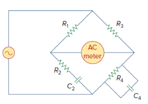
Figure 9.85
Show that when the bridge in Figure 9.85 is balanced the value of frequency is
Explanation of Solution
Given data:
Refer to Figure 9.85 in the textbook.
Formula used:
Write a general expression to calculate the impedance of a resistor.
Here,
Write a general expression to calculate the impedance of a capacitor.
Here,
Write a general expression to calculate the angular frequency.
Here,
Calculation:
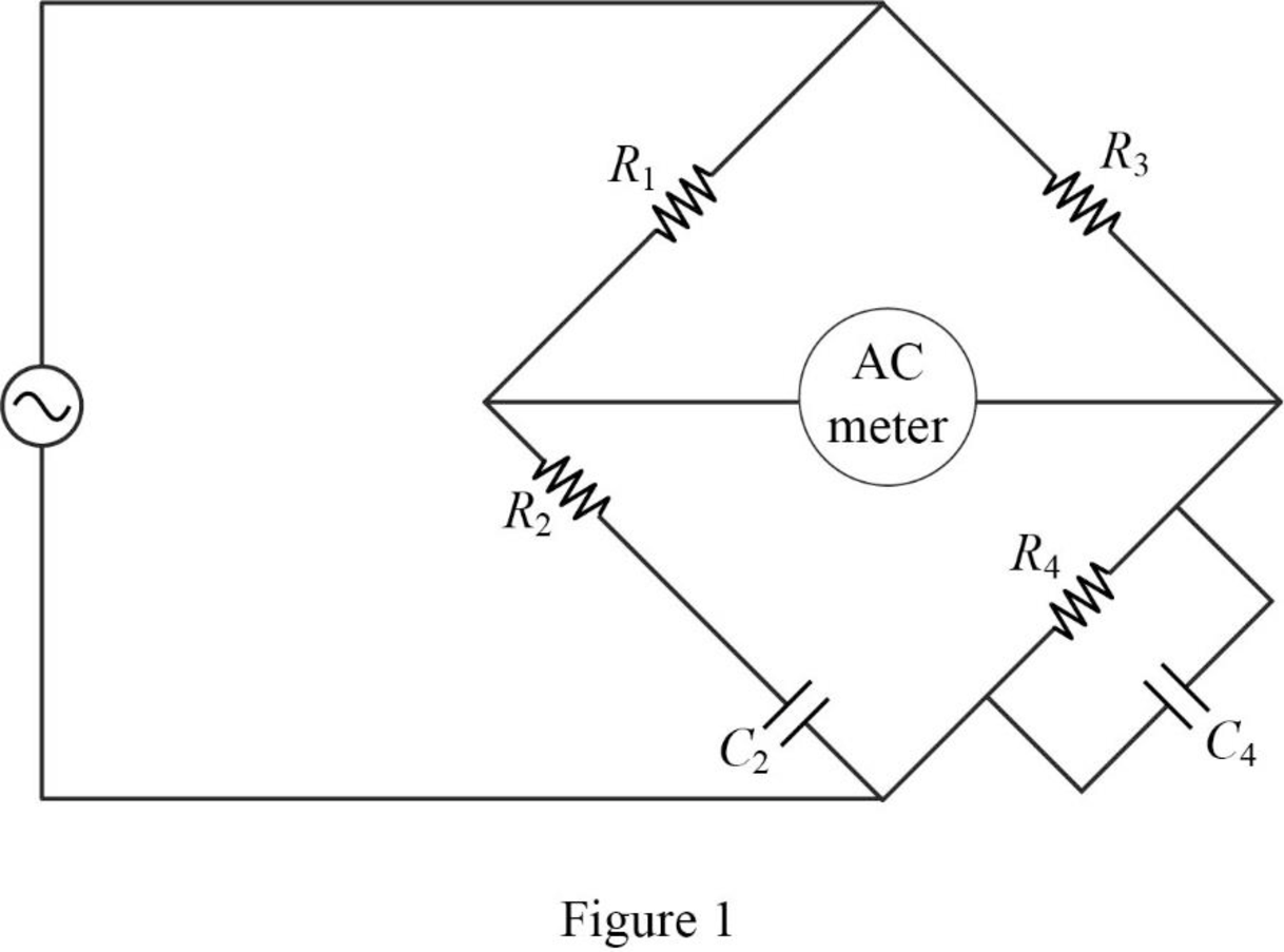
The given circuit is redrawn as shown in Figure 1.
Use equation (1) to find
Use equation (2) to find
Now, the impedance diagram of Figure 1 is drawn as shown in Figure 2.
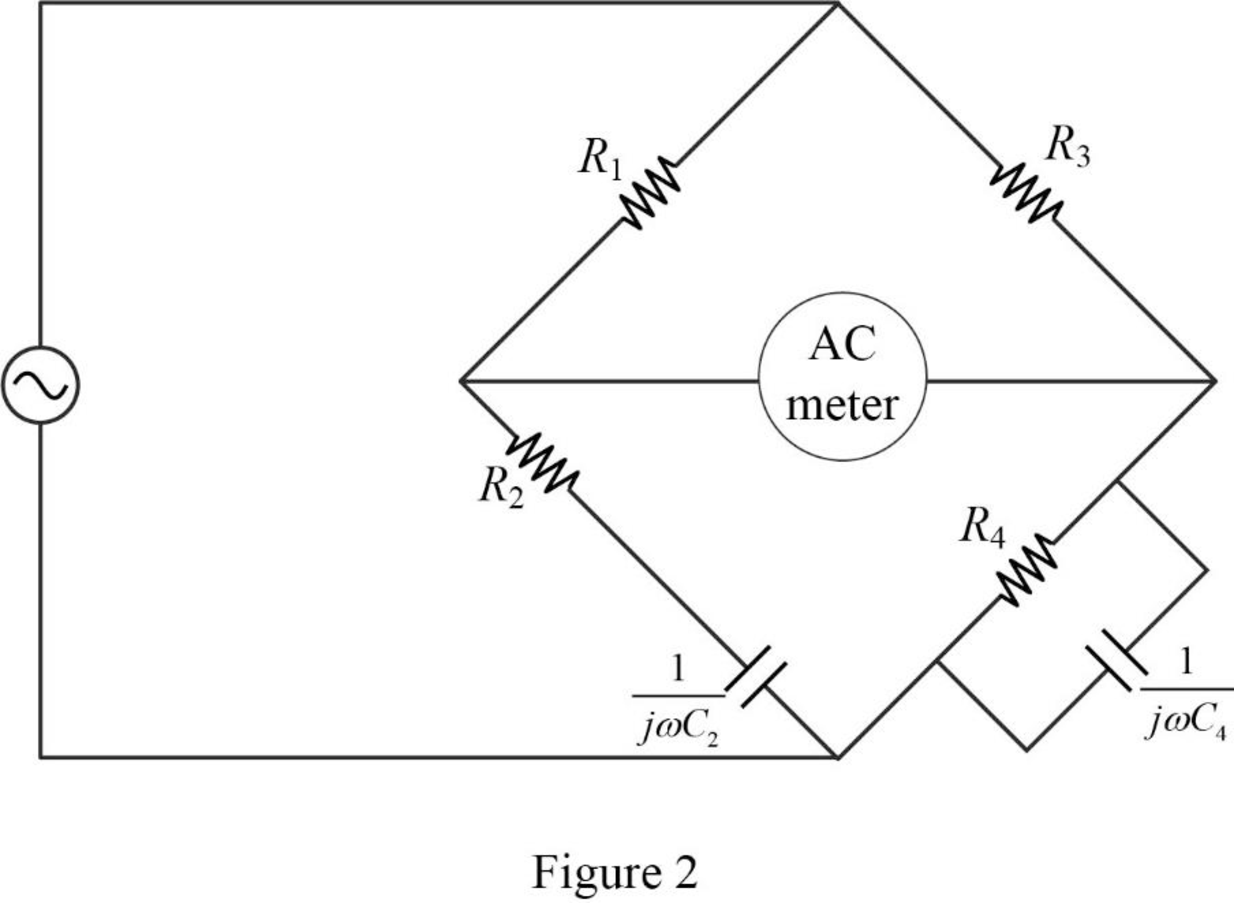
Refer to Figure 2, the impedance of resistor
Therefore, the equivalent impedance
Refer to Figure 2, the impedance of resistor
The equivalent impedance
Simplify the above equation as follows:
Let,
The balance of equation of an ac bridge is,
The above equation as rearranged as follows:
Substitute
Take the conjugate of denominator to rationalize the fraction in left hand side.
Equate the real and imaginary part in above equation.
Divide equation (4) by (5).
Simplify the above equation to find
Rearrange equation (3) to find
Substitute
Conclusion:
Thus, when the bridge is balanced, the value of frequency
Want to see more full solutions like this?
Chapter 9 Solutions
EBK FUNDAMENTALS OF ELECTRIC CIRCUITS


- please solve manually. I need the drawing and the values too. Thank you!arrow_forwardTwo alternators, Y-connected 6.6 kV supply a load of 3000 kW at 0.8 p.f lagging. The synchronous mpedance of first alternator is (0.5+j10) Q/ph and second alternator is (0.4+j12) /ph. First alternator delivers 150 amp at 0.875 lag p.f. The two alterators are shared load equally. Determine the current, p.f., induced e.m.f, load angel, and maximum developed power of each alternator?arrow_forwardA domestic load of 2300 kW at 0.88 p.f lagging and a motors load of 3400 kW at 0.85 p.f lagging are supplied by two alternators operating in parallel. If one alternator is delivering a load of 3300 kW at 0.9 p.f lagging, what will be the output power and p.f of the other alternator?arrow_forward
- Determine the value of Rr that necessary for the circuit in Fig.(2) to operate as an oscillator and then determine the frequency of oscillation. 0.001 F 0.001 F 0.001 F R₁ • 10 ΚΩ R₁ 10 k R • 10 ΚΩarrow_forward(a) For the circuit shown in Figure Q3(a) (RFC and Cc are forbias) (i) (ii) Draw the AC small signal equivalent circuit of the oscillator. From this equivalent circuit derive an equation for fo and the gain condition for the oscillations to start. VDD www RG eee RFC H Cc 北 5 C₁ L 000 C₂ Voarrow_forwardPlease solve this question step by step handwritten solution and do not use chat gpt or any ai toolsfor part ii) you may need to use nodal analysisarrow_forward
- 12.1. Find the steady-state response vo (t) for the network. 00000- 1Ω ww 12 cos(t) V + www 202 1 H 202 1 F + 1Ω νο -arrow_forwardA Three-phase, 12 pole, Y-connected alternator has 108 slots and 14 conductors per slot. The windings are (5/6 th) pitched. The flux per pole is 57 mWb distributed sinusoidally over the pole. If the machine runs at 500 r.p.m., determine the following: (a) The frequency of the generated e.m.f., (b) The distribution factor, (c) The pitch factor, and (d) The phase and line values of the generated e.m.f.?arrow_forwardTwo 3-ph, 6.6 kV, Y-connected, alternators supply a load of 3000 kW at 0.8 p.f. lagging. The synchronou impedance per phase of machine A is (0.5+110) and that of machine B is (0.4 +J12) . The excitation of machine A adjusted so that it delivers 150 A. The load is shared equally between the machines. Determine the armature curre p.f., induced e.m.f., and load angle of each machine?arrow_forward
- Name the circuit below? The output voltage is initially zero and the pulse width is 200 μs. Find the Vout and draw the output waveform? +2.5 V V 247 -2.5 V C 0.01 F Ri W 10 ΚΩarrow_forwardPlease work outarrow_forwardFind Vfinal when Vs up and Vs V. Which LED will light in each case? Red or Green? Justify your answers. Fill the table below. Vs 8 ΚΩ Vos Χρι + 3 ΚΩ www 6 ΚΩ ww 4 ΚΩ Yo www Vo Vec-12 V Nol V final Vm w 3 ΚΩ 5 V 38 ΚΩ R= 1 kQ V -12 V Red LED Green LED Vs Vo Vfinal Which LED is ON? Varrow_forward
 Delmar's Standard Textbook Of ElectricityElectrical EngineeringISBN:9781337900348Author:Stephen L. HermanPublisher:Cengage Learning