
Videos
Find v(t) in the RLC circuit of Fig. 9.48.
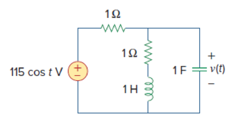
Figure 9.48
Find the value the voltage
Answer to Problem 41P
The value of the voltage
Explanation of Solution
Given date:
Refer to Figure 9.48 in the textbook.
Formula used:
Write the expression to convert the time domain expression into phasor domain.
Here,
A is the magnitude,
t is the time, and
Write the expression to calculate the total phasor current.
Here,
Write the expression to calculate the impedance of the passive elements resistor, inductor and capacitor.
Here,
Calculation:
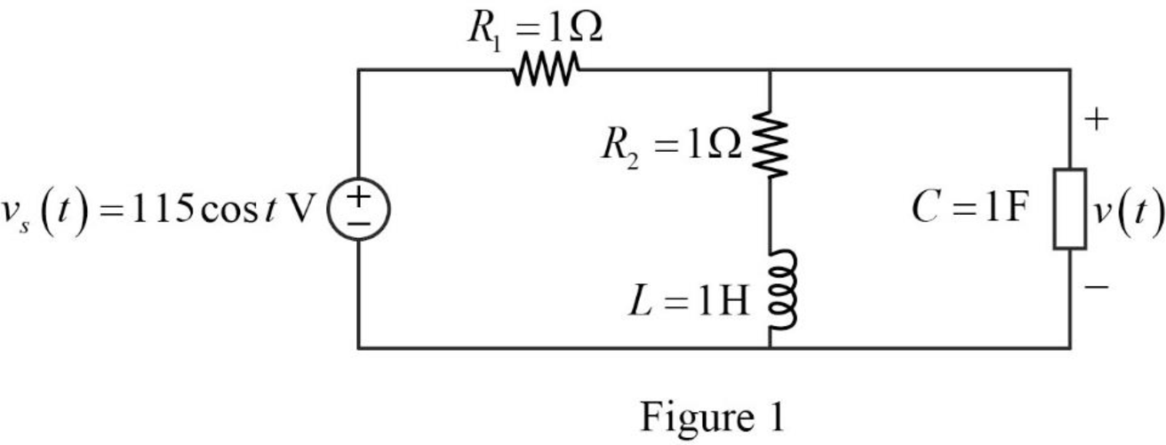
The given RLC circuit is redrawn as Figure 1.
Refer to Figure 1, the source voltage is,
Here, angular frequency
Use the equation (1) to express the above equation in phasor form.
Substitute
Substitute
Substitute
Substitute
The Figure 1 is redrawn as impedance circuit in the following Figure 2.
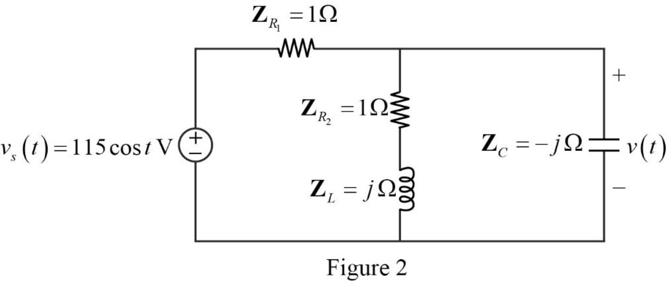
Refer to Figure 2, the series combination of the impedances
Write the expression to calculate the equivalent impedance 1 for the parallel combination as follows.
Here,
Substitute
The reduced circuit of the Figure 2 is drawn as Figure 3.
Refer to Figure 2, the impedances
Write the expression to calculate the equivalent capacitance for the series connected impedances
Here,
Substitute
The reduced circuit of the Figure 3 is drawn as Figure 4.
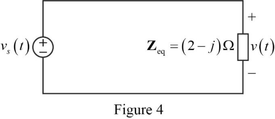
Substitute
Refer to Figure 2, the current through the capacitor is expressed as,
Refer to Figure 2, the voltage across the capacitor is expressed as,
Substitute
Substitute
Use the equation (1) to express the above equation in time domain form.
Substitute
Conclusion:
Thus, the value of the voltage
Want to see more full solutions like this?
Chapter 9 Solutions
EBK FUNDAMENTALS OF ELECTRIC CIRCUITS
Additional Engineering Textbook Solutions
Starting Out with Python (4th Edition)
Elementary Surveying: An Introduction To Geomatics (15th Edition)
Starting Out with Programming Logic and Design (5th Edition) (What's New in Computer Science)
Java: An Introduction to Problem Solving and Programming (8th Edition)
Automotive Technology: Principles, Diagnosis, And Service (6th Edition) (halderman Automotive Series)
Thinking Like an Engineer: An Active Learning Approach (4th Edition)


- 2. A system with unity feedback is shown below. The feed-forward transfer function is G(s), where 5 . G(S) = (+1) Sketch the root locus for the variations in the values of pi. (s+P1)s R(s) C(s) G(s)arrow_forward3. The following closed-loop systems in Fig. 1 and Fig. 2 operate with a damping ratio of 0.707 (=0.707). The system in Fig. 1 does not have a PI controller, while the one in Fig. 2 does. R(s): S Gain Plant R(s) + E(s) 1 C(s) K (s+1)(s+2)(s+10) Fig. 1: Closed-loop system without PI controller Compensator Plant R(s) + E(s) K(s+0.1) S 1 (s+1)(s+2)(s+10) C(s) Fig. 2: Closed-loop system with a practical PI controller a. Please use Matlab to find the intersection point between line and the root locus of the system in Fig. 1. Then find the K value and one complex closed-loop pole corresponding to the intersection point. Calculate the steady-state error. Show the Matlab code in your answer sheet. b. Please use Matlab to find the intersection point between § line and the root locus of the system in Fig. 2. Then find the K value and one complex closed-loop pole associated with the intersection point. Compare the complex closed-loop pole with the one you just found in task a. Are they very…arrow_forward1. Please draw the root locus by hand for the following closed-loop system, where G(s) = s+6 = S-2 s+8 s-2' and H(s) = Find the range of K for stability using Method II in Examples 2 and 3 in Lecture 15. Input R(s) Output C(s) KG(s) H(s)arrow_forward
- 9-1) Lathi & Ding, Prob. P.5.1-10 (a) A first-order-hold circuit can also be used to reconstruct a signal g(t) from its samples. The impulse response of this circuit is h(t) = A ( 2Ts 12 where Ts is the sampling interval. Consider a typical sampled signal ğ(t) and show that this circuit performs the linear interpolation. In other words, the filter output consists of sample tops connected by straight-line segments. Follow the procedure discussed in Sec. 5.1.2 (Fig. 5.6) for a typical signal g(t). (b) Determine the transfer function of this filter and its amplitude response, and compare it with the ideal filter required for signal reconstruction.arrow_forwardI have this rough circuit diagram of a 2 double end trolley light system with a 120 dcv power supply. I would like to know in what way is better to connect the interior lights along with the headlight and door light. Provide the circuit diagram and with its respect connection and the estimated total power rated for the lights. Where: Headlights (2) = #1 and #6Door lights (4) = #2, #4, #5, and #7Platform lights (2) = #3 and #8Interior lights are approximately 20 in quantity. Also, can you say if the components that are in series with the power supply are correct or does it need to be replaced with something else or if it is missing any components.arrow_forwardA domestic load of 2300 kW at 0.88 p.f lagging and a motors load of 3400 kW at 0.85 p.f lagging are supplied by two alternators operating in parallel. If one alternator is delivering a load of 3300 kW at 0.9 p.f lagging, what will be the output power and p.f of the other alternator?arrow_forward
- 9-3) similar to Lathi & Ding, Prob. P.5.2-3 In a satellite radio system, 200 stereo stations are to be packaged in one data stream. For each station, two (left & right) signals of bandwidth 22 kHz are sampled, quantized, and binary-coded into PCM signals. The transmitter then multiplexes the data from the 200 stations into a single stream via TDM and modulates that stream onto a radio carrier using DSB-SC-AM. (a) If the maximum acceptable quantization error is 0.25% of the peak signal voltage, find the minimum number of bits needed for a uniform quantizer. (b) If the sampling rate must be 25% higher than the Nyquist rate, find the minimum bit rate of the multiplexed data stream, based on the quantizer of part (a). (c) If 10% more bits are added for error correction and framing, determine the minimum bandwidth of the radio signal sent to the ground receivers.arrow_forward9-2) similar to Lathi & Ding, Prob. P.5.2-1 A compact disc (CD) records audio signals digitally by using PCM. Assume that the audio signal bandwidth equals 15 kHz. (a) If the Nyquist samples are uniformly quantized into L = 65, 536 levels and then binary-coded, determine the number of binary digits required to encode a sample. (b) if the audio signal has a peak voltage of ±1V and an average signal power of 0.1 V2, find the resulting ratio of signal to quantization noise (SQNR) for the system. (c) Determine the number of binary digits per second (bit/s) required to encode the audio signal. (d) For practical reasons discussed in the text, signals are sampled at a rate well above the Nyquist rate. Practical CDs use 44,100 samples per second. If L = 65,536, determine the number of bits per second required to encode the signal and the minimum bandwidth required to transmit the encoded signal.arrow_forward12.1 Evaluate each of the following integrals: (a) G₁ =√(31³ −4t²+3)[8(t) +28(t − 2)] dt. (b) G2=2(e³t +1)[8(t) −28(t − 2)] dt. 16 (c) G3 = √124t sin(2лt) − 1][§(t − 1)+8(t −6)] dt.|arrow_forward
- 12.3 Express each of the waveforms in Fig. P12.3 (on page667) in terms of step functions and then determine its Laplacetransform. [Recall that the ramp function is related to thestep function by r(t − T) = (t − T) u(t − T).] Assume that allwaveforms are zero for t < 0.arrow_forwardCalculate the torque developed by the motor if Field. excitation is so adjusted as to make the back e.mif twice the applied voltage and α = 16°, Neglecting losses for a 3-phasi 150 KW 2300 V, 50 Hz, 1000 rpm salient Pole synchronous motor has Xd=32 52/Phase and Xy = 2052/phase. 7arrow_forwardASSIGNMENT NO. 6 1. Consider the circuit below with C = 0.02 uF, Ri 100 kr and Rf = 470 k2. The input waveform has T = 0.5 ms and Vp = 8 V. Under steady state conditions, determine the peak-to-peak value of the output voltage.arrow_forward
 Introductory Circuit Analysis (13th Edition)Electrical EngineeringISBN:9780133923605Author:Robert L. BoylestadPublisher:PEARSON
 Delmar's Standard Textbook Of ElectricityElectrical EngineeringISBN:9781337900348Author:Stephen L. HermanPublisher:Cengage Learning
 Programmable Logic ControllersElectrical EngineeringISBN:9780073373843Author:Frank D. PetruzellaPublisher:McGraw-Hill Education
 Fundamentals of Electric CircuitsElectrical EngineeringISBN:9780078028229Author:Charles K Alexander, Matthew SadikuPublisher:McGraw-Hill Education
 Electric Circuits. (11th Edition)Electrical EngineeringISBN:9780134746968Author:James W. Nilsson, Susan RiedelPublisher:PEARSON
 Engineering ElectromagneticsElectrical EngineeringISBN:9780078028151Author:Hayt, William H. (william Hart), Jr, BUCK, John A.Publisher:Mcgraw-hill Education,