
EBK FUNDAMENTALS OF ELECTRIC CIRCUITS
6th Edition
ISBN: 8220102801448
Author: Alexander
Publisher: YUZU
expand_more
expand_more
format_list_bulleted
Videos
Textbook Question
Chapter 9, Problem 52P
If 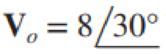 V in the circuit of Fig. 9.59, find Is.
Figure 9.59
Expert Solution & Answer
Want to see the full answer?
Check out a sample textbook solution
Students have asked these similar questions
Design a modulo-11 ripple (asynchronous) up-counter with negative edge-triggered T flip-flops and draw the corresponding logic circuit.
(I)Build the state diagram and extract the state table
(II)Draw the logic circuit
(III)What is the maximum modulus of the counter?
the diagram show 4 motor connected to a k-35 controller. I would like detail explanation to know how the circuit work. Is the controller compatible with the motor? The motor shown is series, parallel or both?
please draw logic diagram please
Chapter 9 Solutions
EBK FUNDAMENTALS OF ELECTRIC CIRCUITS
Ch. 9.2 - Practice Problem 9.1 Given the sinusoid 45 cos(5t...Ch. 9.2 - Practice Problem 9.2 Find the phase angle between...Ch. 9.3 - Prob. 3PPCh. 9.3 - Express these sinusoids as phasors: (a)...Ch. 9.3 - Find the sinusoids corresponding to these phasors:...Ch. 9.3 - If v1=10sint30V and v2=20cost+45V, find v=v1+v2.Ch. 9.3 - Prob. 7PPCh. 9.4 - If voltage v=25sin100t15V is applied to a 50F...Ch. 9.5 - Refer to Fig. 9.17. Determine v(t) and i(t).Ch. 9.7 - Determine the input impedance of the circuit in...
Ch. 9.7 - Calculate vo in the circuit of Fig. 9.27. Figure...Ch. 9.7 - Find I in the circuit of Fig. 9.30. Figure 9.30Ch. 9.8 - Design an RC circuit to provide a 90 lagging phase...Ch. 9.8 - Refer to the RL circuit in Fig. 9.36. If 10 V is...Ch. 9.8 - In the ac bridge circuit of Fig. 9.37, suppose...Ch. 9 - Which of the following is not a right way to...Ch. 9 - A function that repeats itself after fixed...Ch. 9 - Which of these frequencies has the shorter period?...Ch. 9 - If v1 = 30 sin(t + 10) and v2 = 20 sin(t + 50),...Ch. 9 - The voltage across an inductor leads the current...Ch. 9 - The imaginary part of impedance is called:...Ch. 9 - The impedance of a capacitor increases with...Ch. 9 - At what frequency will the output voltage v0(t) in...Ch. 9 - A series RC circuit has VR = 12 V and VC = 5 V....Ch. 9 - A series RCL circuit has R = 30 , XC = 50 , and XL...Ch. 9 - Given the sinusoidal voltage v(t) = 50 cos (30t +...Ch. 9 - A current source in a linear circuit has...Ch. 9 - Express the following functions in cosine form:...Ch. 9 - Design a problem to help other students better...Ch. 9 - Given v1=45sint+30V and v2=50cost30V, determine...Ch. 9 - For the following pairs of sinusoids, determine...Ch. 9 - If f() = cos + j sin , show that f() = ej.Ch. 9 - Calculate these complex numbers and express your...Ch. 9 - Evaluate the following complex numbers and leave...Ch. 9 - Design a problem to help other students better...Ch. 9 - Find the phasors corresponding to the following...Ch. 9 - Let X=440 and Y=2030. Evaluate the following...Ch. 9 - Evaluate the following complex numbers: (a)...Ch. 9 - Simplify the following expression: (a)...Ch. 9 - Evaluate these determinants: (a) 10+j62j351+j (b)...Ch. 9 - Prob. 16PCh. 9 - Two voltages v1 and v2 appear in series so that...Ch. 9 - Obtain the sinusoids corresponding to each of the...Ch. 9 - Using phasors, find: (a) 3cos20t+105cos20t30 (b)...Ch. 9 - A linear network has a current input 7.5cos10t+30A...Ch. 9 - Simplify the following: (a) ft=5cos2t+154sin2t30...Ch. 9 - An alternating voltage is given by v(t) = 55...Ch. 9 - Apply phasor analysis to evaluate the following:...Ch. 9 - Find v(t) in the following integrodifferential...Ch. 9 - Using phasors, determine i(t) in the following...Ch. 9 - Prob. 26PCh. 9 - A parallel RLC circuit has the node equation...Ch. 9 - Determine the current that flows through an 20-...Ch. 9 - Given that vc(0) = 2 cos(155) V, what is the...Ch. 9 - A voltage v(t) = 100 cos(60t + 20) V is applied to...Ch. 9 - A series RLC circuit has R = 80 , L = 240 mH, and...Ch. 9 - Using Fig. 9.40, design a problem to help other...Ch. 9 - A series RL circuit is connected to a 220-V ac...Ch. 9 - What value of will cause the forced response, vo...Ch. 9 - Find the steady-state current i in the circuit of...Ch. 9 - Using Fig. 9.43, design a problem to help other...Ch. 9 - Determine the admittance Y for the circuit in Fig....Ch. 9 - Using Fig. 9.45, design a problem to help other...Ch. 9 - For the circuit shown in Fig. 9.46, find Zeq and...Ch. 9 - In the circuit of Fig. 9.47, find io when: (a) =...Ch. 9 - Find v(t) in the RLC circuit of Fig. 9.48. Figure...Ch. 9 - Calculate vo(t) in the circuit of Fig. 9.49....Ch. 9 - Find current Io in the circuit shown in Fig. 9.50....Ch. 9 - Calculate i(t) in the circuit of Fig. 9.51. Figure...Ch. 9 - Find current Io in the network of Fig. 9.52....Ch. 9 - If vs = 100 sin(10t + 18) V in the circuit of Fig....Ch. 9 - In the circuit of Fig. 9.54, determine the value...Ch. 9 - Given that vs(t) = 20 sin (100t 40) in Fig. 9.55,...Ch. 9 - Find vs (t) in the circuit of Fig. 9.56 if the...Ch. 9 - Determine vx in the circuit of Fig. 9.57. Let...Ch. 9 - If the voltage vo across the 2- resistor in the...Ch. 9 - If V in the circuit of Fig. 9.59, find Is. Figure...Ch. 9 - Find Io in the circuit of Fig. 9.60.Ch. 9 - In the circuit of Fig. 9.61, Find Vs if Io=300A.Ch. 9 - Find Z in the network of Fig. 9.62, given that...Ch. 9 - At = 377 rad/s, find the input impedance of the...Ch. 9 - At = 1 rad/s, obtain the input admittance in the...Ch. 9 - Using Fig. 9.65, design a problem to help other...Ch. 9 - For the network in Fig. 9.66, find Zin. Let = 100...Ch. 9 - Obtain Zin for the circuit in Fig. 9.67. Figure...Ch. 9 - Find Zeq in the circuit in Fig. 9.68. Figure 9.68Ch. 9 - For the circuit in Fig. 9.69, find the input...Ch. 9 - For the circuit in Fig. 9.70, find the value of...Ch. 9 - Find ZT and Vo in the circuit in Fig. 9.71. Let...Ch. 9 - Determine ZT and I for the circuit in Fig. 9.72....Ch. 9 - For the circuit in Fig. 9.73, calculate ZT and...Ch. 9 - At = 103 rad/s, find the input admittance of each...Ch. 9 - Determine Yeq for the circuit in Fig. 9.75. Figure...Ch. 9 - Find the equivalent admittance Yeq of the circuit...Ch. 9 - Find the equivalent impedance of the circuit in...Ch. 9 - Obtain the equivalent impedance of the circuit in...Ch. 9 - Calculate the value of Zab in the network of Fig....Ch. 9 - Determine the equivalent impedance of the circuit...Ch. 9 - Design an RL circuit to provide a 90 leading phase...Ch. 9 - Design a circuit that will transform a sinusoidal...Ch. 9 - For the following pairs of signals, determine if...Ch. 9 - Refer to the RC circuit in Fig. 9.81. (a)...Ch. 9 - A coil with impedance 8 + j6 is connected in...Ch. 9 - (a) Calculate the phase shift of the circuit in...Ch. 9 - Consider the phase-shifting circuit in Fig. 9.83....Ch. 9 - The ac bridge in Fig. 9.37 is balanced when R1 =...Ch. 9 - A capacitance bridge balances when R1 = 100 , R2 =...Ch. 9 - An inductive bridge balances when R1 = 1.2 k, R2 =...Ch. 9 - The ac bridge shown in Fig. 9.84 is known as a...Ch. 9 - The ac bridge circuit of Fig. 9.85 is called a...Ch. 9 - The circuit shown in Fig. 9.86 is used in a...Ch. 9 - The network in Fig. 9.87 is part of the schematic...Ch. 9 - A series audio circuit is shown in Fig. 9.88. (a)...Ch. 9 - An industrial load is modeled as a series...Ch. 9 - An industrial coil is modeled as a series...Ch. 9 - Figure 9.91 shows a series combination of an...Ch. 9 - A transmission line has a series impedance of and...Ch. 9 - A power transmission system is modeled as shown in...
Knowledge Booster


Learn more about
Need a deep-dive on the concept behind this application? Look no further. Learn more about this topic, electrical-engineering and related others by exploring similar questions and additional content below.Similar questions
- Please draw the diagrams please thank youarrow_forwardA plane wave propagating through a medium with &,,-8 μr = 2 has: E = 0.5 e-j0.33z sin (108 t - ẞz) ax V/m. Determine (a) ẞ (b) The loss tangent (c) Wave impedance (d) Wave velocity (e) H fieldarrow_forward2) The phase voltage at the terminals of a balanced three-phase Y-connected load is 2400 V. The load has an impedance of 16+j12 2/6 and is fed from a line having an impedance of 0.10+j0.80 2/6. The Y- connected source at the sending end of the line has a positive phase sequence and an internal impedance of 0.02+j0.16 2/6. Use the a-phase voltage at the load as the reference. a) Construct the a-phase equivalent circuit of the system b) Calculate the line currents IaA, IbB, and Icc c) Calculate the phase voltages at the terminals of the source, Van, Vbn, Vcn- d) Calculate the line voltages at the source, Vab, Vbc and Vca. e) Calculate the internal phase-to-neutral voltages at the source, Va'n, Vb'n, Ve'n,arrow_forward
- 1) • A balanced three-phase circuit has the following characteristics: Y-Y connected The line voltage at the source is Vab = 120√3(0°V • The phase sequence is positive The line impedance is 2+ j3 2/0 The load impedance is 28 + j37 02/0 a) [4 pts] Draw the single phase equivalent circuit for the a-phase. b) [2 pts] Calculate the line current IaA in the a-phase. c) [4 pts] Calculate the line voltage VAB at the load in the a-phase.arrow_forwardFind the value of V0 using the superposition method. Note: The answer is V0=-428.57mvarrow_forwardDon't use ai to answer I will report you answerarrow_forward
- If a trolley has a 120VDC power supply intended to power auxiliary components such as lights, buzzers, and speakers, how would the speakers connect to that power system? I understand that speakers typically operate on AC, so what is the most efficient way to connect them to the 120VDC setup? Additionally, could you provide an estimate of the power output for the speakers?arrow_forwardChoose the appropriate answer 1) Maximum dimension of antenna is 0.5m and operating frequency is 9 GHz, thus the radius of reactive near field region is 0.562m 1.265m 2.526m 3.265m 2) If distance between transmitter and receiver is 2km and the signal carrier frequency is 300kHz Rapidly time-varying fields DC field Quasi-static field None 3) The polarization mismatch factor for horizontal polarization wave incident on +z axis is is if the antenna polarization is circular 0.5 зав 0.707 1 4) Ez 0 and Hz #0 (HE modes): This is the case when neither E nor H field is transverse to the direction of wave propagation. They are sometimes referred to as TEM hybrid modes TM TE 5) The normalized radiation intensity of an antenna is represented by: U(6)=cos²(0) cos2 (30), w/s Half-power beamwidth HPBW is...... 28.75 10 0 14.3arrow_forwardChoose the best answer of the following: 1- quasi-static electromagnetic field is the a) low frequency b)high frequency c) time independent d) none of the above 2- Displacement current is taken to be negligible (compared to the conduction current) if a) σ>>wε b)σ << wɛ c) σ =0 d) (a and c) 3- The transmission line act as inductor when it terminated by: a) Open circuit load b) short circuit load c)matched load d)none of the above 4- The scattering aperture equals to the effective aperture when the antenna is: a) Complex conjugate matching b) short circuit c) open circuit d) none of the above 5- The isotropic point source has directivity of: a) Infinity b)1 c) 0 d)1.5arrow_forward
- I selected a DC-DC converter capable of delivering 120 VDC from a 600 VDC input. When I reached out to the manufacturer, they asked for the total power consumption the converter would need to handle.To estimate this, I calculated the power requirements for the components that will use the 120 VDC supply: interior lighting, end lights, and buzzers. The breakdown is as follows:- Light Bulbs: 16 bulbs at 10 W each = 160 W- Buzzers: 2 buzzers at 5 W each = 10 W- End Lights: 2 lights at 15 W each = 30 W This results in a total estimated power demand of 200 W.My concern is whether I should request a higher wattage rating for the converter to provide sufficient tolerance and ensure the system operates efficiently without risking an overload. Note: The DC power system is designed specifically for a trolleyarrow_forwardChoose the best answer 1. The minimum value of the directivity of an antenna is.......... a) Unity b) Zero 2. Very low signal strength in antenna. a) Minor lobes b) Null c) Infinite d) None c) Antenna patterns d) Major lobes 3. the maximum directivity of an antenna that normalized far field pattern is given by? 0≤0≤ and 0 ≤≤π/2,3л/2≤ p ≤ 2π E(0, 4) = {(sin 0 ((sin cos² ) 1/2 0 is a) 7.07dB b) 7.7dB elsewhere c) 8.7dB d) 9dB 4. the depth of penetration of 1 MHz wave in sea water which has conductivity mhos/meter and permeability approximately equal to that of free space is a) 25mm b) 25cm c)25m 5. The free space media can be considered as _ a) Lossy media b) lossless media c) good conductor 6. The input impedance is equal to the load impedance when a) l = 2 b)1=22 c)=4 d) 25km d) a and c .... d) a and barrow_forwardQ.1. choose the appropriate answer 1- When neither E nor H field is transverse to the direction of wave propagation. They are sometimes referred to as ...... a) hybrid mode b) TM mode c) TME modes d) TEM mode 2- If PLF-0 dB means......... a) Power is lost 100% b) Power is lost 0% c) Power is lost 50% d) none of the above 3. The half wave dipole is widely used in more applications compared to other linear antenna lengths, that is because..... a) It has high gain b) its easy matching to coaxial 75 Ohm cable c) low loss d) it has small size 4- The mode distribution for the end view waveguide shown below is a) TM12 b) TM21 c) TE20 end view d) TE02 5. When circular right hand polarized wave incident upon a horizontally polarized wave the PLF is a) 0 b)1 c)0.5 d)0.707arrow_forward
arrow_back_ios
SEE MORE QUESTIONS
arrow_forward_ios
Recommended textbooks for you
 Delmar's Standard Textbook Of ElectricityElectrical EngineeringISBN:9781337900348Author:Stephen L. HermanPublisher:Cengage Learning
Delmar's Standard Textbook Of Electricity
Electrical Engineering
ISBN:9781337900348
Author:Stephen L. Herman
Publisher:Cengage Learning
Inductors Explained - The basics how inductors work working principle; Author: The Engineering Mindset;https://www.youtube.com/watch?v=KSylo01n5FY;License: Standard Youtube License