
Concept explainers
Videos
For the transistor network in Fig. 9.143.
a. Find the Thevenin equivalent circuit for that portion of the network to the left of the base (B) terminal.
b. Using the fact that
c. Using the results of parts (a) and (b), calculate the base current
if
d. What is the voltage
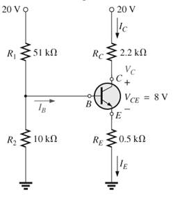
Fig,9.143
Want to see the full answer?
Check out a sample textbook solution
Chapter 9 Solutions
Introductory Circuit Analysis (13th Edition)
Additional Engineering Textbook Solutions
Electric Circuits. (11th Edition)
Automotive Technology: Principles, Diagnosis, And Service (6th Edition) (halderman Automotive Series)
Fluid Mechanics: Fundamentals and Applications
Thinking Like an Engineer: An Active Learning Approach (4th Edition)
BASIC BIOMECHANICS
Starting Out with Python (4th Edition)


- I need help in construct a method in matlab to find the voltage of VR1 to VR4, rhe current, and the power base on that circuit Nominal or Theortical: E1 = 3V , E2 = 9V, E3 = 1.5V R1 =10Kohm, R2 =2Kohm, R3 =1Kohm, R4 =16Kohmarrow_forwardI have a question based on the mesh anaylsis, why does current around R1 and the same as R3?arrow_forward1. Compute the output signals S and T for the circuit. Input signals P = 1, Q = 1, and R = 1. C₁ P half-adder #1 R AND -S C₁₂ half-adder #2 2. Use 8-bit representations to compute the following sum. Show all work. 57+(-118) 3. Find a counterexample to show that the following statement is false: 1 Vx Є R, x>- χ T 4. Is the proposed negation correct? If yes, provide a sound reasoning. If not, provide a sound reasoning and write the correct negation. Statement: For all integers n, if n² is even then n is even. Negation: For all integers n, if n² is even then n is not even.arrow_forward
- not use aiarrow_forward2. (35 points) Use you program to investigative properties of a four step linear pathway. Just extend the model given in question 1 to include an additional two species x2 and x3. You can assume simple irreversible mass-action kinetic on each reaction. I recommend you use the following values for the rate constants: 1 = 0.6; k2 = 1.8; k3 = 0.5; k40.04. This will enable you to more easily answer the following questions. You can also assume that the input is the source X and you can set its value to one. You may find that the plot of the phase change at x3 is broken at -180 degrees because it wraps around. To avoid this you can use the method: phase = np.unwrap(phase) to make sure the phase plot is continuous. [10] i) Compute and show the Bode plots for x1, x2 and x3 with respect to the input Xo. [5] ii) Do you see a pattern with the maximum phase shifts as you move from x₁ to x3? [10] iii) Can you explain this pattern? [5] iv) What would you predict would be the maximum phase shift for…arrow_forwardPlease answer all The zombies showed up while you were sleeping! The zombie alarm you built goes off as they open the door. You jolt awake to see an alpha-zombie charging through the door. The alphas are zombies that turned all of the zombies in its army. If you can take down this one zombie, all the others pouring into the room should fall as well. Luckily, your group was prepared for this eventuality. Another member of your team has constructed the zombie shocker circuit shown in Figure 5, using some batteries for the voltage source, some rusty metal for the resistors and a coil of wire for the inductor. The switch is just you pulling apart two wires to open the circuit (while holding them by their insulated sheaths). 1. Construct the circuit shown in Figure 15 in the Circuit JS simulator. 2. Start the simulation with switch SW1 in the closed position. You’ve been charging this circuit all night, so you’ll want to let the circuit run for a while (roughly 30 seconds at max…arrow_forward
- Please answer all questions 1. Calculate the values of the following without using Circuit JS. Assume the circuit has reached steady state. Show these calculations: a) Voltage across and current through C1. b) Voltage across and current through L1. c) Voltage across and current through R5. 2. Construct the circuit in the Circuit JS simulator [1]. 3. Perform a simulation and determine the following values. Record them. Allow the circuit to reach steady state. a) Voltage across and current through C1. b) Voltage across and current through L1. c) Voltage across and current through R5. 4. Include a screen shot of the simulator window (including showing the values listed above). 5. Answer the following questions: a) In a DC circuit, what does a capacitor look like? b) In a DC circuit, what does an inductor look like?arrow_forwardHelp with homework, with the extra portion part too pleasearrow_forwardRedraw the previous circuit and add a 24 V red lamp to indicate the relay coil is on, a 230 V yellow lamp to indicate the solenoid is on, green lamp to indicate the solenoid is off. Use only one relay, which has multiple contacts.arrow_forward
- Design a control circuit so a 24 V relay , start button, and a stop push button (on/off with memory) operates an electromechanical relay to control a 230 V solenoid Next, Redraw the previous circuit and add a 24 V red lamp to indicate the relay coil is on, a 230 V yellow lamp to indicate the solenoid is on, green lamp to indicate the solenoid is off. Use only one relay, which has multiple contacts.arrow_forwardplease answer it handwritten , thanks! will give thumbs uparrow_forwardEXAMPLE 6.3 Suppose the Fourier transform of a pulse is as follows: (1-a) Ть. 2Ть H(f) = < α (To) (-Tof+ 1 +a (1-a) (1+α) ·<|f|≤· 2 2ть 2Ть (1+α) 0, <\f\ 2Ть where 0≤a≤1. Show that this pulse in both time and frequency domains satisfies the Nyquist criterion.arrow_forward
 Introductory Circuit Analysis (13th Edition)Electrical EngineeringISBN:9780133923605Author:Robert L. BoylestadPublisher:PEARSON
 Delmar's Standard Textbook Of ElectricityElectrical EngineeringISBN:9781337900348Author:Stephen L. HermanPublisher:Cengage Learning
 Programmable Logic ControllersElectrical EngineeringISBN:9780073373843Author:Frank D. PetruzellaPublisher:McGraw-Hill Education
 Fundamentals of Electric CircuitsElectrical EngineeringISBN:9780078028229Author:Charles K Alexander, Matthew SadikuPublisher:McGraw-Hill Education
 Electric Circuits. (11th Edition)Electrical EngineeringISBN:9780134746968Author:James W. Nilsson, Susan RiedelPublisher:PEARSON
 Engineering ElectromagneticsElectrical EngineeringISBN:9780078028151Author:Hayt, William H. (william Hart), Jr, BUCK, John A.Publisher:Mcgraw-hill Education,