
Concept explainers
Videos
Consider a modified form of Couette flow in which there are two immiscible fluids sandwiched between two infinitely lone and wide, parallel flat plates (Fig. 9-101). The flow is steady, incompressible, parallel, and laminar. The top plate moves at velocity V to the right, and the bottom plate is stationary. Gravity acts in the -z-direction (downward in the figure). There is no forced pressure gradient pushing the fluids through the channel-the flow is setup solely by viscous effects created by the moving upper plate. You may ignore surface tension effects and assume that dre interface is horizontal. The pressure at the bottom of the flow (z = 0) is equal to
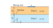
FIGURE P9-101
(a)
The six appropriate boundary condition on both velocity and pressure.
Answer to Problem 101P
The first boundary conditions is
The second boundary conditions is
The third boundary conditions is
The fourth boundary conditions is
The fifth boundary conditions is
The sixth boundary conditions is
Explanation of Solution
Given information:
The following figure shows that two parallel flat plates.
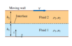
Figure-( 1)
Assume, at the point of wall and fluid, the velocity of the fluid is equal to zero.
Write the expression for velocity of the fluid 1,
Here, the velocity of fluid 1 is
Assume, the velocity of the fluid 2 at the free surface of the wall is equal to the velocity of the moving plates.
Write the expressions for the velocity of fluid 2.
Here, the velocity of fluid 2 is
Write the expression for velocity at interface.
Write the expression for rate of shear stress.
Here, the kinematic coefficient of fluid is
Write the expression for the shear stress acting on fluid 1.
Here, the kinematic coefficient of fluid 1 is
Write the expression for the shear stress acting on fluid 2.
Here, the kinematic coefficient of fluid 2 is
Write the expression for the rate of shear stress at interface.
Write the expression for pressure at the bottom of the flow,
Here, the pressure is
Write the expression for the pressure at the interface of fluid 1.
Here, the pressure at the fluid 1 is
Write the expression for the pressure at the interface of fluid 2.
Here, the pressure at the fluid 1 is
Assume, at the interface of the fluid the pressure cannot have discontinuity and the surface is ignored.
Write the expression for the pressure at interface of fluid.
Conclusion:
The first boundary conditions is
The second boundary conditions is
The third boundary conditions is
The fourth boundary conditions is
The fifth boundary conditions is
The sixth boundary conditions is
(b)
The expression for the velocity of fluid 1.
The expression for the velocity of fluid 2.
Answer to Problem 101P
The expression for the velocity of fluid 1 is
The expression for the velocity of fluid 2 is
Explanation of Solution
Write the expression for
Here, the velocity of flow for fluid 1 is
Write the expression for
Here, the velocity of flow for fluid 2 is
Calculation:
Integrate Equation (XIII) with respect to
Here, the constant is
Integrate Equation (XIII) with respect to
Here, the constant is
Integrate Equation (XIV) with respect to
Here, the constant is
Integrate Equation (XIV) with respect to
Here, the constant is
Substitute
Substitute
Substitute
Substitute
Substitute
Differentiate Equation (XXI) with respect to
Substitute
Substitute
Substitute
Substitute
Conclusion:
The expression for the velocity of fluid 1 is
The expression for the velocity of fluid 2 is
(c)
The expression for the pressure of fluid 1.
The expression for the pressure of fluid 2.
Answer to Problem 101P
The expression for the pressure of fluid 1 is
The expression for the pressure of fluid 2 is
Explanation of Solution
Write the expression for
Here, the density of the fluid 1 is
Write the expression for
Here, the density of the fluid 2 is
Calculation:
Integrate Equation (XXV) with respect to
Here, the constant is
Substitute
Substitute
Integrate Equation (XXVI) with respect to
Here, the constant is
Substitute
Substitute
Substitute
Conclusion:
The expression for the pressure of fluid 1 is
The expression for the pressure of fluid 2 is
(d)
The plot
Answer to Problem 101P
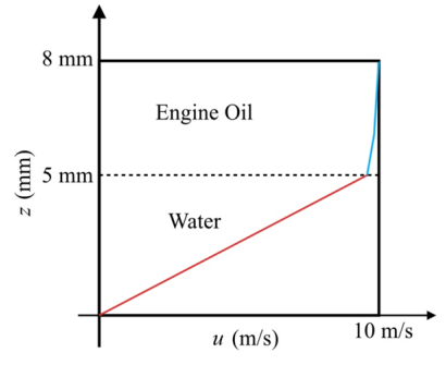
The following Figure-(2) represents the velocities of fluid 1 and 2.
Explanation of Solution
Given information:
The fluid 1 be water and the fluid 2 be unused engine oil, at
The following figure shows that two parallel flat plates.
Write the expression for the velocity of fluid 1.
Here, the distance is
Write the expression for the velocity of fluid 2.
Calculation:
Refer the Table-A-3E, "Properties of saturated water", to obtain the value of dynamic viscosity of water is
Refer the Table-A-7E, "Properties of the atmosphere at high attitude", to obtain the value of dynamic viscosity of unused engine oil is
Substitute
Substitute
The following graph represents the velocities of fluid 1 and 2.

Figure-(2)
In the fluid 1 the linear curve is increasing with respect to the velocity of flow and height of fluid 1. In the fluid 2 the curve is increasing with respect to the velocity of flow and height of fluid 2.
Conclusion:
The following Figure-(2) represents the velocities of fluid 1 and 2.

Want to see more full solutions like this?
Chapter 9 Solutions
Fluid Mechanics: Fundamentals and Applications
Additional Engineering Textbook Solutions
Vector Mechanics For Engineers
Electric Circuits. (11th Edition)
Concepts Of Programming Languages
Thermodynamics: An Engineering Approach
Mechanics of Materials (10th Edition)
Modern Database Management


- Solve this problem and show all of the workarrow_forwardSolve this problem and show all of the workarrow_forwarddraw the pneumatic circuit to operate a double-acting cylinder with: 1. Extension: Any of two manual conditions plus cylinder fully retracted, → Extension has both meter-in and meter-out, 2. Retraction: one manual conditions plus cylinder fully extended, → Retraction is very fast using quick exhaust valve.arrow_forward
- Correct answer is written below. Detailed and complete solution with fbd only. I will upvote, thank you. Expert solution plsarrow_forwardCorrect answer is written below. Detailed and complete solution with fbd only. I will upvote, thank you.arrow_forwardCorrect answer is written below. Detailed and complete solution with fbd only. I will upvote, thank you.arrow_forward
- Correct answer is written below. Detailed and complete solution only with fbd. I will upvote, thank you.arrow_forwardCorrect answer is written below. Detailed and complete solution only. I will upvote, thank you.arrow_forwardCorrect answer is written below. Detailed and complete solution with fbd only. I will upvote, thank you.arrow_forward
- Correct answer is written below. Detailed and complete solution only. I will upvote, thank you.arrow_forwardCorrect answer is written below. Detailed and complete solution with fbd only. I will upvote, thank you.arrow_forwardCorrect answer is written below. Detailed and complete solution only. I will upvote, thank you.arrow_forward
 Elements Of ElectromagneticsMechanical EngineeringISBN:9780190698614Author:Sadiku, Matthew N. O.Publisher:Oxford University Press
 Mechanics of Materials (10th Edition)Mechanical EngineeringISBN:9780134319650Author:Russell C. HibbelerPublisher:PEARSON
 Thermodynamics: An Engineering ApproachMechanical EngineeringISBN:9781259822674Author:Yunus A. Cengel Dr., Michael A. BolesPublisher:McGraw-Hill Education
 Control Systems EngineeringMechanical EngineeringISBN:9781118170519Author:Norman S. NisePublisher:WILEY
 Mechanics of Materials (MindTap Course List)Mechanical EngineeringISBN:9781337093347Author:Barry J. Goodno, James M. GerePublisher:Cengage Learning
 Engineering Mechanics: StaticsMechanical EngineeringISBN:9781118807330Author:James L. Meriam, L. G. Kraige, J. N. BoltonPublisher:WILEY