Videos
a)
The rate of exergy destroyed during the process and the exit temperature
a)
Answer to Problem 64P
The rate of exergy destroyed during the process is
The exit temperature
Explanation of Solution
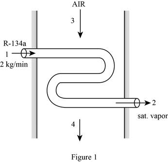
Draw the schematic diagram of the flow of refrigerant-134a through evaporator section as shown in Figure (1).
Write the expression for the mass balances equation for the heat exchanger.
Here, mass flow rate of refrigerant at inlet is
Since net mass flow rate of refrigerant-134a and air through system is 0.
From Figure (1), the mass flow rate of refrigerant-134a at
Here, initial and final mass flow rate of refrigerant at
From Figure (1), the mass flow rate of air at
Here, mass flow rate of air at
Write the expression for the enthalpy at state 1
Write the expression for the entropy at state 1
Write the expression for the mass flow rate of air
Here, gas constant of air is
Write the expression for energy balance for the heat exchanger
Here, rate of net energy transfer in to the control volume is
Substitute 0 for
Here, mass flow rate at
Write the expression for the entropy balance for the steady flow system as;
Here, rate of entropy generation is
At steady state, rate of change in entropy of the system is zero.
Substitute 0 for
Here, entropy at
Write the expression for the change between state 4 entropy
Here, temperature at state
Write the expression for the exergy destroyed rate during the process
Here, dead state temperature is
Conclusion:
Refer to Table A-12, “Saturated refrigerant-134a-Pressure table”, obtain the following properties at the pressure
Here, enthalpy of saturated liquid is
Substitute
Substitute
Refer to Table A-12, “Saturated refrigerant-134a-Pressure table”, obtain the following properties at the pressure
Here, enthalpy at state 2 is
From the Table A-2, “Ideal-gas specific heats of various common gases table”, select the gas constant of air gas
Substitute
At steady state, rate of change in internal energy of the system is zero.
From the Table A-2, “Ideal-gas specific heats of various common gases table”, select the constant pressure specific heat
Substitute
Thus, the exit temperature
Substitute
Substitute
Substitute
Thus, the rate of exergy destroyed during the process is
b)
The exit temperature of the air and the rate of exergy destroyed during the process without insulation.
b)
Answer to Problem 64P
The exit temperature of the air without insulation is
The rate of exergy destroyed during the process without insulation is
Explanation of Solution
Write the expression for the state 4 temperature
Here, heat gain is from the surrounding
Write the expression for the entropy balance For an extended system as;
Conclusion:
Substitute
Thus, the exit temperature of the air is
substitute
Substitute
Substitute
Thus, the rate of exergy destroyed during the process is
Want to see more full solutions like this?
Chapter 8 Solutions
Thermodynamics: An Engineering Approach


- Finite Element Analysisarrow_forwardan experimental research station is constructed on a concrete slab floor. The heat loss from the floor slab is significant, given the cold environment, and is measured to be 5 kW. The edges of the floor slab are insulated with a 60 mm thickness of cellular glass insulation. The width of this insulation at the floor slab is 0.9 m. To avoid excessive fuel consumption, the station air temperature is maintained at a slightly cool temperature of 18ºC. The station is constructed in a square shape, to keep the surface area to volume ratio low; the horizontal dimensions of the floor of the station are 20 m by 20 m. The number of occupants in the research station varies between 5 and 20, depending on the research workload.a) Determine the design outdoor temperature that was used in designing the research station.b) If the floor dimensions of the station are changed to 15 m by 25 m, would the design outdoor temperature that was used in designing the research station from part (a) change? If so,…arrow_forwardFinite element analysisarrow_forward
- a station is constructed on a concrete slab floor. The heat loss from the floor slab is significant, given the cold environment, and is measured to be 5 kW. The edges of the floor slab are insulated with a 60 mm thickness of cellular glass insulation. The width of this insulation at the floor slab is 0.9 m. To avoid excessive fuel consumption, the station air temperature is maintained at a slightly cool temperature of 18ºC. The station is constructed in a square shape, to keep the surface area to volume ratio low; the horizontal dimensions of the floor of the station are 20 m by 20 m. The number of occupants in the research station varies between 5 and 20, depending on the research workload.a) Determine the design outdoor temperature that was used in designing the research station.b) If the floor dimensions of the station are changed to 15 m by 25 m, would the design outdoor temperature that was used in designing the research station from part (a) change? If so, what would it be?…arrow_forwardFinite Element Analysisarrow_forwardFinite Element Analysisarrow_forward
- A small auditorium that can accommodate 30 people allows smoking. The design engineers of the auditorium assume that the smokers each are responsible for an average of 50 micrograms per minute of tobacco smoke being added to the auditorium space. The volumetric flow rate of recirculated room air is 200 cfm. Outdoor air is also supplied, and is mixed with the recirculated room air. The system has a ventilation effectiveness of 80%. In an effort to maintain the level of particulate matter from the tobacco smoke in the auditorium to no more than 5.5 micrograms per cubic foot, filters with an effective efficiency of 90% are added to the ventilation system downstream of the point in the system where outdoor air and recirculated room air are mixed. a) What is the necessary volumetric flow rate (in cfm) for the supply outdoor air? Assume the outdoor air is clean. b) The outdoor air taken into the system becomes contaminated with tobacco smoke due to a leak in an adjacent building’s…arrow_forwardroom to be maintained with a dry-bulb temperature of 72ºF and 30% relative humidity. The room has a sensible heat factor of 0.8 and a total hourly heating load of 200,000 Btu. A flow rate of 1000 cfm of outdoor air (at 20% relative humidity and a dry-bulb temperature of 40ºF) is used. In order to maintain adequate comfort, the supply air to the room is set to a dry-bulb temperature of 120ºF. To humidify the air, steam with a specific enthalpy of 1150 Btu per pound is utilized.Determine the wet bulb temperature, specific enthalpy, and volumetric flow rate of the supply air to the room. Evaluate the increase in dry-bulb temperature as the air is sensibly heated, and the mass flow rate (in lb/hr) of steam required during the latent heating of the air. Calculate the heat added to the room during sensible heating (i.e., excluding humidification).arrow_forwardPlease can you help with the attached question? Many thanksarrow_forward
- Which of the following sequences converge and which diverge? 20) an = 21) a = n! 106 1/(Inn) 3n+1 " 22) a = 3n-1 1/n x" 23) a = , x>0 2n+1 3" x 6" 24) an 25) a, = tanh(n) = 2" xn! n² 1 26) a = sin 2n-1 n 27) a = tan(n) 1 28) a = 1 3 ++ (Inn) 200 2" 29) an n 30) =n-√√n²-n 1"1 31) a == dx nixarrow_forwardWhich of the following sequences converge and which diverge? n+1 6) a = 1- 2n (-1)+1 7) a = 2n-1 2n 8) an = n+1 1 9) a = sin + 2 n sin n 10) a = n 11) an = 12) a = 13) an 14) an 15) an 16) an n 2" In(n+1) = 81/n n n =(1+7)" = = 10n 3 n 1/n 17) an = In n 1/n n' 18) a =√4"narrow_forwardQu 3 Nickel (Ni) single crystal turbine blades burn less fuel at higher temperatures because blades are grown on [110] closed packed direction. Nickel (Ni) at 20°C is FCC, and has an atomic radius, R, of 0.125 nm. Draw a reduced-sphere unit cell for this crystal and draw and label the vector [I 10], starting from the origin (0, 0, 0). a) Calculate the length of the vector [| 10] in nanometers. Express your answer in nanometers to one significant figure. b) Calculate the linear density of Nickel in the [| 1 0] direction in [atom/nm]. Express your answer in atoms/nm to one significant figure. show all work problemsarrow_forward
 Elements Of ElectromagneticsMechanical EngineeringISBN:9780190698614Author:Sadiku, Matthew N. O.Publisher:Oxford University Press
 Mechanics of Materials (10th Edition)Mechanical EngineeringISBN:9780134319650Author:Russell C. HibbelerPublisher:PEARSON
 Thermodynamics: An Engineering ApproachMechanical EngineeringISBN:9781259822674Author:Yunus A. Cengel Dr., Michael A. BolesPublisher:McGraw-Hill Education
 Control Systems EngineeringMechanical EngineeringISBN:9781118170519Author:Norman S. NisePublisher:WILEY
 Mechanics of Materials (MindTap Course List)Mechanical EngineeringISBN:9781337093347Author:Barry J. Goodno, James M. GerePublisher:Cengage Learning
 Engineering Mechanics: StaticsMechanical EngineeringISBN:9781118807330Author:James L. Meriam, L. G. Kraige, J. N. BoltonPublisher:WILEY