
Precision Machining Technology (MindTap Course List)
2nd Edition
ISBN: 9781285444543
Author: Peter J. Hoffman, Eric S. Hopewell, Brian Janes
Publisher: Cengage Learning
expand_more
expand_more
format_list_bulleted
Concept explainers
Videos
Textbook Question
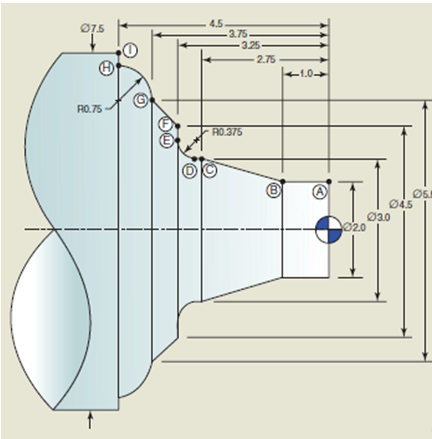
Chapter 8.3, Problem 1RQ
Write the X- and Z-axis coordinates for the part show n. Use the diametral method in the X-axis.
Expert Solution & Answer
Want to see the full answer?
Check out a sample textbook solution
Students have asked these similar questions
reaction at a is 1.6 wL (pos)
handwritten solutions only please. correct answers upvoted
1
8
4
Add numbers so that the sum of any
row or column equals .30 Use only
these numbers:
.1.2.3.4.5.6.10.11.12.12.13.14.14
Uppgift 2 (9p)
I77777
20 kN
10 kN/m
4
[m]
2
2
Bestäm tvärkrafts- och momentdiagram för balken i figuren ovan. Extrempunkter ska anges
med både läge och värde i diagrammen.
Chapter 8 Solutions
Precision Machining Technology (MindTap Course List)
Ch. 8.1 - What is an ATC?Ch. 8.1 - What is an MCU and what is its function?Ch. 8.1 - Briefly describe a ball screw and a linear guide.Ch. 8.1 - Explain the benefits of using the absolute...Ch. 8.1 - Explain the benefits of using the incremental...Ch. 8.1 - Which coordinate system uses an angle and a...Ch. 8.1 - What is the name for the type of motor used to...Ch. 8.1 - Supposing a programmer, using absolute mode,...Ch. 8.1 - What is a modal code?Ch. 8.1 - What is another name for the Cartesian coordinate...
Ch. 8.1 - List four G-codes and describe their functions. a....Ch. 8.1 - List four M-codes and describe their functions. a....Ch. 8.1 - What is the name of the character that ends each...Ch. 8.1 - Explain the purpose of the safe-start portion of a...Ch. 8.2 - Name the two primary machine axes on most CNC...Ch. 8.2 - Explain the difference between a turning center...Ch. 8.2 - List the three common types of live toolholders....Ch. 8.2 - Name three major collet styles used in...Ch. 8.2 - Name three types of workholding devices for...Ch. 8.2 - Name three major styles of turning machines....Ch. 8.2 - Explain why some workholding devices can be run at...Ch. 8.2 - Explain the difference between an OD grooving tool...Ch. 8.2 - When machining workpieces made from bar stock,...Ch. 8.2 - Describe how a sub-spindle can be used to increase...Ch. 8.2 - How does a Swiss turning center differ from a...Ch. 8.3 - Write the X- and Z-axis coordinates for the part...Ch. 8.3 - To perform a facing cut using a tool with a nose...Ch. 8.3 - Explain the difference between rigid tapping and...Ch. 8.3 - How must the feed rate for tapping using a...Ch. 8.3 - Describe what happens to a concave radius (fillet)...Ch. 8.3 - Describe what happens to an outside chamfer when...Ch. 8.3 - If a G1 code command is programmed partway through...Ch. 8.3 - List and briefly describe the two methods for...Ch. 8.3 - Explain in your own words the difference between...Ch. 8.3 - In your own words, describe a canned cycle.Ch. 8.3 - List two types of canned cycles besides roughing...Ch. 8.4 - What machine mode is generally used to manually...Ch. 8.4 - MDI stands for _________ ___________ ________.Ch. 8.4 - Which must be set first, the tool geometry offset...Ch. 8.4 - What is the process called where a program is sent...Ch. 8.4 - Explain the purpose of homing.Ch. 8.4 - What is the process called when a new program is...Ch. 8.4 - When setting up a machine to run a program that...Ch. 8.4 - What does MCS stand for?Ch. 8.4 - What is used to adjust the clamping pressure of...Ch. 8.4 - What does MCS stand for?Ch. 8.4 - What does WCS stand for?Ch. 8.4 - A workpiece offset is the distance from __________...Ch. 8.5 - Explain the difference between a machining center...Ch. 8.5 - Name the two major types of ATCs and briefly...Ch. 8.5 - What are the two basic types of tapping...Ch. 8.5 - What are the three most common styles of collets...Ch. 8.5 - What are the two basic types of tapping...Ch. 8.5 - Prob. 6RQCh. 8.5 - A programmable indexing fixture creates a fourth...Ch. 8.5 - A _______ ________ uses interchangeable tooling...Ch. 8.5 - Briefly describe a tombstone used for CNC...Ch. 8.5 - A custom ______ can be designed and built to hold...Ch. 8.5 - The combination of the machining operations...Ch. 8.6 - What are the three major axes used during CNC mill...Ch. 8.6 - What command would be given to turn on the spindle...Ch. 8.6 - What G-code designates IPM feed rate mode? IPR...Ch. 8.6 - What is the purpose of a clearance plane in CNC...Ch. 8.6 - What is the purpose of work coordinate systems?Ch. 8.6 - Briefly define linear interpolation.Ch. 8.6 - If during the last operation on a part, a G1 code...Ch. 8.6 - Briefly describe the use of I and J for the arc...Ch. 8.6 - Write two blocks of code that could be used to...Ch. 8.6 - Briefly explain the difference between rigid and...Ch. 8.6 - Define the initial plane for a canned drilling or...Ch. 8.6 - A G98 in a canned cycle sets the return point to...Ch. 8.6 - A _____ code is used to cancel a canned cycle.Ch. 8.6 - What two codes are used to activate automatic...Ch. 8.6 - What two codes are used to activate automatic...Ch. 8.6 - What code is used to cancel automatic cutter...Ch. 8.7 - Which must be set first, a work offset or a tool...Ch. 8.7 - What mode is used to manually enter programs into...Ch. 8.7 - What is the process called when a program is sent...Ch. 8.7 - Explain what may occur that makes it necessary to...Ch. 8.7 - Explain the purpose of homing.Ch. 8.7 - What is the process called when a new program is...Ch. 8.7 - What are two actions that can be taken during the...Ch. 8.7 - When automatic cutter radius compensation is used...Ch. 8.7 - Which machine mode allows short, temporary program...Ch. 8.7 - Which machine mode is used to run the machine...Ch. 8.7 - What are the two controls on the machine's control...Ch. 8.7 - What control panel feature can be used to slow a...Ch. 8.8 - Prob. 1RQCh. 8.8 - Prob. 2RQCh. 8.8 - What are the three primary steps in creating a CNC...Ch. 8.8 - Prob. 4RQCh. 8.8 - What is the definition of entity?Ch. 8.8 - Why should a toolpath be verified on the screen of...Ch. 8.8 - What is a post-processor used for?Ch. 8.8 - What is it called when mutiple touching entities...Ch. 8.8 - What type of cutting tool is usually used for...
Knowledge Booster


Learn more about
Need a deep-dive on the concept behind this application? Look no further. Learn more about this topic, mechanical-engineering and related others by exploring similar questions and additional content below.Similar questions
- **Problem 8-45.** The man has a mass of 60 kg and the crate has a mass of 100 kg. If the coefficient of static friction between his shoes and the ground is \( \mu_s = 0.4 \) and between the crate and the ground is \( \mu_c = 0.3 \), determine if the man is able to move the crate using the rope-and-pulley system shown. **Diagram Explanation:** The diagram illustrates a scenario where a man is attempting to pull a crate using a rope-and-pulley system. The setup is as follows: - **Crate (C):** Positioned on the ground with a rope attached. - **Rope:** Connects the crate to a pulley system and extends to the man. - **Pulley on Tree:** The rope runs over a pulley mounted on a tree which redirects the rope. - **Angles:** - The rope between the crate and tree forms a \(30^\circ\) angle with the horizontal. - The rope between the tree and the man makes a \(45^\circ\) angle with the horizontal. - **Man (A):** Pulling on the rope with the intention of moving the crate. This arrangement tests the…arrow_forwardplease solve this problems follow what the question are asking to do please show me step by steparrow_forwardplease first write the line action find the forces and them solve the problem step by steparrow_forward
- please solve this problem what the problem are asking to solve please explain step by step and give me the correct answerarrow_forwardplease help me to solve this problem step by steparrow_forwardplease help me to solve this problem and determine the stress for each point i like to be explained step by step with the correct answerarrow_forward
- please solve this problem for me the best way that you can explained to solve please show me the step how to solvearrow_forwardplese solbe this problem and give the correct answer solve step by step find the forces and line actionarrow_forwardplease help me to solve this problems first write the line of action and them find the forces {fx=0: fy=0: mz=0: and them draw the shear and bending moment diagram. please explain step by steparrow_forward
- please solve this problem step by step like human and give correct answer step by steparrow_forwardPROBLEM 11: Determine the force, P, that must be exerted on the handles of the bolt cutter. (A) 7.5 N (B) 30.0 N (C) 52.5 N (D) 300 N (E) 325 N .B X 3 cm E 40 cm cm F = 1000 N 10 cm 3 cm boltarrow_forwardUsing the moment-area theorems, determine a) the rotation at A, b) the deflection at L/2, c) the deflection at L/4. (Hint: Use symmetry for Part a (θA= - θB, or θC=0), Use the rotation at A for Parts b and c. Note that all deformations in the scope of our topics are small deformation and for small θ, sinθ=θ).arrow_forward
arrow_back_ios
SEE MORE QUESTIONS
arrow_forward_ios
Recommended textbooks for you
 Precision Machining Technology (MindTap Course Li...Mechanical EngineeringISBN:9781285444543Author:Peter J. Hoffman, Eric S. Hopewell, Brian JanesPublisher:Cengage Learning
 International Edition---engineering Mechanics: St...Mechanical EngineeringISBN:9781305501607Author:Andrew Pytel And Jaan KiusalaasPublisher:CENGAGE L
Precision Machining Technology (MindTap Course Li...
Mechanical Engineering
ISBN:9781285444543
Author:Peter J. Hoffman, Eric S. Hopewell, Brian Janes
Publisher:Cengage Learning
International Edition---engineering Mechanics: St...
Mechanical Engineering
ISBN:9781305501607
Author:Andrew Pytel And Jaan Kiusalaas
Publisher:CENGAGE L
Introduction To Engineering Drawing; Author: EzEd Channel;https://www.youtube.com/watch?v=z4xZmBpXIzQ;License: Standard youtube license