
Concept explainers
Videos
The resistance of loop 2 is greater than that loop l. (The loop are made from different materials.)
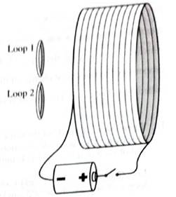
1. Is there a current induced through the wire of either of the loops:
• before the switch is closed? Explain.
• just after the switch is closed? Explain.
• a long after the switch is closed? Explain.
2. For the period of time that there is a current included through the wire of the loops, find the direction of the current.
3. The ratio of the induced currents for the two loops is found by experiment to be equal to the inverse of the ratio of the resistances of the loops.
What does this observation imply about the ratio of the induced emf in loop 1 to the induced emf in loop 2?
(1)
To Identify:
Induced current through wire of the loops as per the given conditions:
- Before the switch is closed.
- After when the switch is closed.
- After a long-time when the switch is closed.
Explanation of Solution
Introduction:
According to Faradays’ law, an e.m.f is induced in a loop of wire if there is a rate of change in flux passing through the wire.
Where,
Case1: Before the switch is closed:
Before the switch is closed, there is no current flowing in solenoid (bigger loop) that can produce changing magnetic field. Hence, there is no change in flux in the small loops. Therefore, there is no induced current in small coils.
Case 2: After the switch gets closed:
Just after the switch is closed, the current in the solenoid (bigger loop) goes from zero to maximum which makes the magnetic field lines passing through the small loops change. Hence, due to change in flux, there will be induced current in them. The loop with higher resistance will be associated with less induced current.
Case 3: After longtimewhen the switch isclosed:
After long time the switch is closed, there is constant current in solenoid (bigger loop) that produces constant magnetic field. Hence, there is no change in flux in the small loops. Therefore, there is no current in small loops.
Conclusion:
Therefore, following Faraday’s law, there is an induced current in small coils just when switch is closed and is zero for other cases.
(2)
To Find
The direction current induced through a wire of the loops.
Explanation of Solution
Introduction:
According to Lenz’s law, the induced emf will form a magnetic field which counteracts the change in flux.
By seeing the sign of the battery (current flows from positive to negative terminal) and using the right-hand rule, the direction of magnetic field induced in the greater loop must be from left to right. When switch is closed, then the induced current in small loop is in such a way that decreases the magnetic flux produced by the larger loop, hence, the induced current is in clockwise while seeing the loop from right. When switch is opened, the induced current will flow in anticlockwise direction.
Conclusion:
Therefore, the current induced through a wire of the loop will be such that it will oppose the change in flux produced by the bigger loop.
(3)
To Explain:
The ratio of induced emf in the loop 1to the loop 2.
Answer to Problem 1aT
Ratio of emf induced in loop 1to loop 2 is equal.
Explanation of Solution
Introduction:
According to Faradays’ law, an e.m.f is induced in a loop of wire if there is a rate of change in flux passing through the wire.
Where,
The induced emf depends on the rate of change in flux. Considering the area of the small loops same, the change in magnetic flux will be same for both the loops. Therefore, the induced emf will be same.
The induced current will be different in both the loops though, as the resistance of the loop 2 is greater than the loop 1.
Conclusion:
Therefore, induced emf will be same in both smaller loops.
Want to see more full solutions like this?
Chapter 8 Solutions
Tutorials in Introductory Physics
Additional Science Textbook Solutions
College Physics: A Strategic Approach (3rd Edition)
Microbiology: An Introduction
Chemistry: Structure and Properties (2nd Edition)
Human Anatomy & Physiology (2nd Edition)
Cosmic Perspective Fundamentals
Biology: Life on Earth (11th Edition)


- What are the expected readings of the ammeter and voltmeter for the circuit in the figure below? (R = 5.60 Ω, ΔV = 6.30 V) ammeter I =arrow_forwardsimple diagram to illustrate the setup for each law- coulombs law and biot savart lawarrow_forwardA circular coil with 100 turns and a radius of 0.05 m is placed in a magnetic field that changes at auniform rate from 0.2 T to 0.8 T in 0.1 seconds. The plane of the coil is perpendicular to the field.• Calculate the induced electric field in the coil.• Calculate the current density in the coil given its conductivity σ.arrow_forward
- An L-C circuit has an inductance of 0.410 H and a capacitance of 0.250 nF . During the current oscillations, the maximum current in the inductor is 1.80 A . What is the maximum energy Emax stored in the capacitor at any time during the current oscillations? How many times per second does the capacitor contain the amount of energy found in part A? Please show all steps.arrow_forwardA long, straight wire carries a current of 10 A along what we’ll define to the be x-axis. A square loopin the x-y plane with side length 0.1 m is placed near the wire such that its closest side is parallel tothe wire and 0.05 m away.• Calculate the magnetic flux through the loop using Ampere’s law.arrow_forwardDescribe the motion of a charged particle entering a uniform magnetic field at an angle to the fieldlines. Include a diagram showing the velocity vector, magnetic field lines, and the path of the particle.arrow_forward
- Discuss the differences between the Biot-Savart law and Coulomb’s law in terms of their applicationsand the physical quantities they describe.arrow_forwardExplain why Ampere’s law can be used to find the magnetic field inside a solenoid but not outside.arrow_forward3. An Atwood machine consists of two masses, mA and m B, which are connected by an inelastic cord of negligible mass that passes over a pulley. If the pulley has radius RO and moment of inertia I about its axle, determine the acceleration of the masses mA and m B, and compare to the situation where the moment of inertia of the pulley is ignored. Ignore friction at the axle O. Use angular momentum and torque in this solutionarrow_forward
- A 0.850-m-long metal bar is pulled to the right at a steady 5.0 m/s perpendicular to a uniform, 0.650-T magnetic field. The bar rides on parallel metal rails connected through a 25-Ω, resistor (Figure 1), so the apparatus makes a complete circuit. Ignore the resistance of the bar and the rails. Please explain how to find the direction of the induced current.arrow_forwardFor each of the actions depicted, determine the direction (right, left, or zero) of the current induced to flow through the resistor in the circuit containing the secondary coil. The coils are wrapped around a plastic core. Immediately after the switch is closed, as shown in the figure, (Figure 1) in which direction does the current flow through the resistor? If the switch is then opened, as shown in the figure, in which direction does the current flow through the resistor? I have the answers to the question, but would like to understand the logic behind the answers. Please show steps.arrow_forwardWhen violet light of wavelength 415 nm falls on a single slit, it creates a central diffraction peak that is 8.60 cm wide on a screen that is 2.80 m away. Part A How wide is the slit? ΟΙ ΑΣΦ ? D= 2.7.10-8 Submit Previous Answers Request Answer × Incorrect; Try Again; 8 attempts remaining marrow_forward
 Physics for Scientists and Engineers: Foundations...PhysicsISBN:9781133939146Author:Katz, Debora M.Publisher:Cengage Learning
 College PhysicsPhysicsISBN:9781305952300Author:Raymond A. Serway, Chris VuillePublisher:Cengage Learning
 College PhysicsPhysicsISBN:9781285737027Author:Raymond A. Serway, Chris VuillePublisher:Cengage Learning
 College PhysicsPhysicsISBN:9781938168000Author:Paul Peter Urone, Roger HinrichsPublisher:OpenStax College
 Physics for Scientists and Engineers, Technology ...PhysicsISBN:9781305116399Author:Raymond A. Serway, John W. JewettPublisher:Cengage Learning