
(a)
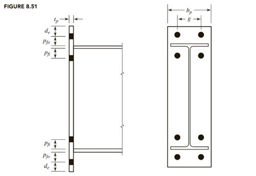
The design of a four-bolt unstiffened end-plate connection for a
Answer to Problem 8.8.3P
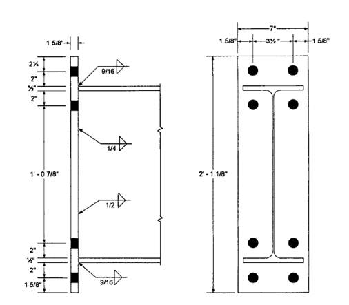
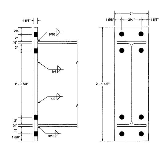
9/16-in. fillet weld at each flange.
¼-in. fillet weld on each side of the web in the tension region.
½-in. fillet weld on each side of the web between mid-depth and the compression flange.
Explanation of Solution
Given:
A992 steel for members
A36 steel for the end plate
Group A pretensioned bolts
Formula used:
Calculation:
From the
From the dimensions and properties tables
Workable gauge = 3.50 in.
For the bolt pitch, try
For the gauge distance, use the workable gauge g = 3.50 in.
Required bolt diameter:
Try
Moment strength based on bolt strength:
Therefore, use
Determine end-plate width:
Minimum
The minimum plate width is
Maximum effective end-plate width =
Try
Determine the required plate thickness:
Therefore, use the original value of
Required
Try
Beam flange force:
The shear yield strength of the end plate is
Shear rupture strength of end plate:
Check bolt shear:
The compression side bolts must be capable of resisting the entire vertical shear.
For 4 bolts,
Try
For 4 bolts,
Recompute the plate dimensions:
For
Minimum
The minimum plate width is
Maximum effective end-plate width =
Use the currently selected width of
Because the bolt size has increased, check the shear rupture strength of the end plate:
Check bearing in the plate at the compression side bolts.
For the outer bolts,
The upper limit is
Therefore, use
Since the inner bolts are not near an edge or adjacent bolts, the outer bolts control.
The total bearing strength is
Check bearing in the column flange:
Use
The upper limit is
Therefore, use
The total bearing strength is
The plate length, using detailing dimensions and the notation of figure given below from the textbook (Steel design), is
Use a
Beam flange to plate weld design:
The flange force is
AISC Design Guide 4 recommends that the minimum design flange force should be 60% of the flange yield strength:
Minimum
Therefore, use the actual flange force of 203.1 kips.
The flange weld length is
The weld strength is
where D is the weld size in sixteenths of an inch and the factor of 1.5 accounts for the direction of the load on the weld. If we equate the weld strength to the flange force,
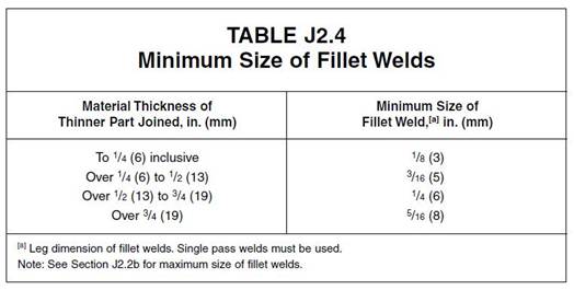
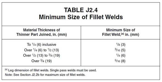
From AISC Table J2.4, the minimum weld size is ¼-in. (based on the thickness of the flange, which is the thinner connected part).
Use a 9/16-in. fillet weld at each flange.
Beam web to plate weld design:
To develop the yield stress in the web near the tension bolts, let
Use a ¼-in. fillet weld on each side of the web in the tension region.
The applied shear of
- From the mid-depth to the compression flange.
From the inner row of tension bolts plus
- to the compression flange:
Equating the weld strength to the required shear strengths, we get
From AISC Table J2.4, the minimum weld size is 3/16-in.
Use a ½-in. fillet weld on each side of the web between mid-depth and the compression flange.
The design is summarized in the figure below:
Conclusion:
Use a
(b)
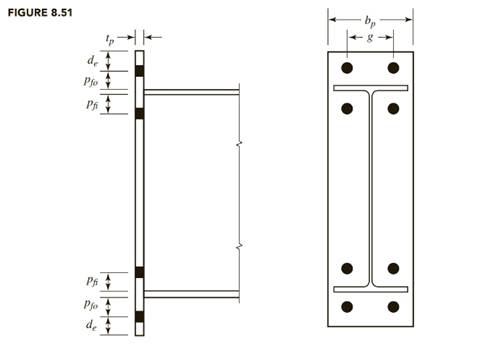
The design of a four-bolt unstiffened end-plate connection for a
Answer to Problem 8.8.3P
9/16-in. fillet weld at each flange.
¼-in. fillet weld on each side of the web in the tension region
½-in. fillet weld on each side of the web between mid-depth and the compression flange.
Explanation of Solution
Given:
A992 steel for members
A36 steel for the end plate
Group A pretensioned bolts
Formula used:
Calculation:
From the
From the dimensions and properties tables
Workable gauge = 3.50 in.
For the bolt pitch, try
For the gauge distance, use the workable gauge g = 3.50 in.
Required bolt diameter:
Try
Moment strength based on bolt strength:
Therefore, use
Determine end-plate width:
Minimum
The minimum plate width is
Maximum effective end-plate width =
Try
Determine the required plate thickness:
Therefore, use the original value of
Required
Try
Beam flange force:
The shear yield strength of the end plate is
Shear rupture strength of end plate:
Check bolt shear:
The compression side bolts must be capable of resisting the entire vertical shear.
For 4 bolts,
Try
For 4 bolts,
Recompute the plate dimensions:
For
Minimum
The minimum plate width is
Maximum effective end-plate width =
Use the currently selected width of
Because the bolt size has increased, check the shear rupture strength of the end plate:
Check bearing in the plate at the compression side bolts.
For the outer bolts,
The upper limit is
Therefore, use
Since the inner bolts are not near an edge or adjacent bolts, the outer bolts control.
The total bearing strength is
Check bearing in the column flange:
Use
The upper limit is
Therefore, use
The total bearing strength is
The plate length, using detailing dimensions and the notation of figure given below from the textbook, is
Use a
Beam flange to plate weld design:
The flange force is
AISC Design Guide 4 recommends that the minimum design flange force should be 60% of the flange yield strength:
Minimum
Therefore, use the actual flange force of 135.4 kips.
The flange weld length is
The weld strength is
where D is the weld size in sixteenths of an inch and the factor of 1.5 accounts for the direction of the load on the weld. If we equate the weld strength to the flange force,
From AISC Table J2.4, the minimum weld size is ¼-in. (based on the thickness of the flange, which is the thinner connected part).
Use a 9/16-in. fillet weld at each flange.
Beam web to plate weld design:
To develop the yield stress in the web near the tension bolts, let
Use a ¼-in. fillet weld on each side of the web in the tension region.
The applied shear of
- From the mid-depth to the compression flange.
From the inner row of tension bolts plus
- to the compression flange:
Equating the weld strength to the required shear strengths, we get
From AISC Table J2.4, the minimum weld size is 3/16-in.
Use a ½-in. fillet weld on each side of the web between mid-depth and the compression flange.
The design is summarized in the figure below:
Conclusion:
Use a
Want to see more full solutions like this?
Chapter 8 Solutions
Bundle: Steel Design, Loose-leaf Version, 6th + Mindtap Engineering, 1 Term (6 Months) Printed Access Card

- Consider a pool of saturated water at atmospheric pressure. The base of the pool is made of thick polished copper square plate of length 1 m. To generate steam, exhaust gas is flowing underneath and parallel to the base plate with velocity 3 m/s and average temperate of 1090°C. The bottom surface the plate is at constant temperature of 110°. Use the properties of air for exhaust gas. a) Determine the boiling heat transfer rate. b) Determine the temperature of the top surface of the plate. Comment on the results. c) Examine the impact of your assumptions on your solutions. (what will change if any of the assumptions is not valid?)arrow_forward-The axial deflection pipe in inches. -The lateral deflection of the beam in inches -The total deflection of the beam like structure in inches ? all to 4 sig figs AI did not help. as i input what i get im not sure if its a rounding error or what.arrow_forward1. For the foundation shown below: Qapp = 60 kips (Load obtained from structural engineer) 1.5 ft G.W.T. 3 ft Poorly Graded Sand (SP): Ym 115 pcf (above G.W.T.) Ysat 125 pcf (below G.W.T.) c' = 0, ' = 35° K Square footing, 4' x 4' Foundation Dimension Information: 1-ft x 1-ft square concrete column. 1-ft thick "foot" flanges. Yconc=150 pcf *Assume weight of reinforcing steel included in unit weight of concrete. *Assume compacted backfill weighs the same as in-situ soil. Assume this foundation is being designed for a warehouse that had a thorough preliminary soil exploration. Using the general bearing capacity equation: a. Calculate the gross applied bearing pressure, the gross ultimate bearing pressure, and determine if the foundation system is safe using a gross bearing capacity ASD approach. Please include the weight of the foundation, the weight of the backfill soil, and the effect of the uplift pressure caused by the presence of the water table in your bearing capacity…arrow_forward
- ٢٥ ٠٥:٤٠١٠ 2025 ChatGPT VivaCut Onet Puzzle مسلم X Excel JPG I❤> PDF Copilot Chat Bot PDF2IMG iLovePDF NokoPrint O.O StudyX ☑ W CapCut Candy Crush DeepSeek Word ☐ Saga 啡 AcadAl ل TikTokarrow_forwardRefer to the figure below. Given: L = 7 m, y = 16.7 kN/m², and ø' = 30°. L L3 ση Sand γ $' D T LA L σε σε IN P Sand 1. Calculate the theoretical depth of penetration, D. (Enter your answer to three significant figures.) D= m 2. Calculate the maximum moment. (Enter your answer to three significant figures.) Mmax kN-m/marrow_forwardWhy is it important for construction project managers to be flexible when dealing with the many variable factors that pop up in a project?arrow_forward
- What are some reasons for why a company would accelerate a construction project?arrow_forwardFor the design of a shallow foundation, given the following: Soil: ' = 20° c' = 52 kN/m² Unit weight, y = 15 kN/m³ Modulus of elasticity, E, = 1400 kN/m² Poisson's ratio, μs = 0.35 Foundation: L=2m B=1m Df = 1 m Calculate the ultimate bearing capacity. Use the equation: 1 - qu = c' NcFcs Fcd Fcc +qNqFqsFqdFqc + ½√BN√Fãs F√dƑxc 2 For '=20°, Nc = 14.83, N₁ = 6.4, and N₁ = 5.39. (Enter your answer to three significant figures.) qu = kN/m²arrow_forwardA 2.0 m wide strip foundation carries a wall load of 350 kN/m in a clayey soil where y = 15 kN/m³, c' = 5.0 kN/m² and ' = 23°. The foundation depth is 1.5 m. For ' = 23°: Nc = 18.05; N₁ = 8.66; Ny = = = 8.20. Determine the factor of safety using the equation below. qu= c' NcFcs FcdFci+qNqFqsFq 1 F + gd. 'qi 2 ·BN√· FF γί Ysyd F (Enter your answer to three significant figures.) FS =arrow_forward
 Steel Design (Activate Learning with these NEW ti...Civil EngineeringISBN:9781337094740Author:Segui, William T.Publisher:Cengage Learning