
Theory and Design for Mechanical Measurements
6th Edition
ISBN: 9781118881279
Author: Richard S. Figliola, Donald E. Beasley
Publisher: WILEY
expand_more
expand_more
format_list_bulleted
Videos
Textbook Question
Chapter 8, Problem 8.37P
The thermocouple circuit shown in Figure 8.49 measures the temperature Tj. The voltmeter limits of error are given as
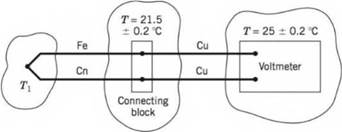
Figure 8.49 Thermocouple circuit for Problem 8.37.
Limits of error: ±0.05% (95%) of reading +15 pV at 25°C
Resolution: 5 pV
Give a best estimate for the temperature T\, if the output voltage is 9 mV.
Expert Solution & Answer
Want to see the full answer?
Check out a sample textbook solution
Students have asked these similar questions
(read image)
(read image)
(read me)
Chapter 8 Solutions
Theory and Design for Mechanical Measurements
Ch. 8 - Prob. 8.1PCh. 8 - Fixed temperature points in the International...Ch. 8 - Answers to the following questions may be found in...Ch. 8 - Calculate the resistance of a platinum wire that...Ch. 8 - Plot the resistance of a platinum wire that is 5 m...Ch. 8 - An RTD forms one arm of a Wheatstone bridge, as...Ch. 8 - An RTD forms one arm (/?4) of a Wheatstone bridge,...Ch. 8 - Research and describe current state-of-the-art...Ch. 8 - Prob. 8.9PCh. 8 - 8.10 Estimate the required level of uncertainty in...
Ch. 8 - 8.11 A thermistor is placed in a 100 °C...Ch. 8 - Prob. 8.12PCh. 8 - Prob. 8.13PCh. 8 - The thermocouple circuit in Figure 8.45 represents...Ch. 8 - The thermocouple circuit in Figure 8.45 represents...Ch. 8 - The thermocouple circuit in Figure 8.45 is...Ch. 8 - 8.17 a. The thermocouple shown in Figure 8.46a...Ch. 8 - Prob. 8.18PCh. 8 - Prob. 8.19PCh. 8 - A temperature measurement requires an uncertainty...Ch. 8 - A temperature difference of 3.0 °C is measured...Ch. 8 - Complete the following table for a J-type...Ch. 8 - Complete the following table for a T-type...Ch. 8 - Prob. 8.24PCh. 8 - 8.25 You are employed as a heating, ventilating,...Ch. 8 - A J-type thermocouple for use at temperatures...Ch. 8 - A J-type thermocouple is calibrated against an RTD...Ch. 8 - A beaded thermocouple is placed in a duct in a...Ch. 8 - Consider a welded thermocouple bead that...Ch. 8 - Prob. 8.30PCh. 8 - Prob. 8.31PCh. 8 - Consider the typical construction of a sheathed...Ch. 8 - An iron-constantan thermocouple is placed in a...Ch. 8 - Figure 8.48 Schematic diagram for Problems 8.33,...Ch. 8 - Figure 8.48 Schematic diagram for Problems 8.33,...Ch. 8 - 8.36 In Example 8.5, an uncertainty value for Rf...Ch. 8 - The thermocouple circuit shown in Figure 8.49...Ch. 8 - Prob. 8.38PCh. 8 - 8.39 A thin-film heat flux sensor employs a K-type...Ch. 8 - A thin-film heat flux sensor has a sensitivity uV...Ch. 8 - 8.41 A T-type thermopile is used to measure...Ch. 8 - 8.42 A T-type thermocouple referenced to 0 °C is...Ch. 8 - A T-type thermocouple referenced to 0 °C develops...Ch. 8 - 8.44 A temperature measurement system consists of...
Knowledge Booster


Learn more about
Need a deep-dive on the concept behind this application? Look no further. Learn more about this topic, mechanical-engineering and related others by exploring similar questions and additional content below.Similar questions
- (read me)arrow_forward(read image)arrow_forwardQu. 13 What are the indices for the Direction 2 indicated by vector in the following sketch? Qu. 14 Determine the indices for the direction A and B shown in the following cubic unit cell. please show all work step by step from material engineeringarrow_forward
- The thin-walled open cross section shown is transmitting torque 7. The angle of twist ₁ per unit length of each leg can be determined separately using the equation 01 = 3Ti GLIC 3 where G is the shear modulus, ₁ is the angle of twist per unit length, T is torque, and L is the length of the median line. In this case, i = 1, 2, 3, and T; represents the torque in leg i. Assuming that the angle of twist per unit length for each leg is the same, show that T= Lic³ and Tmaz = G01 Cmax Consider a steel section with Tallow = 12.40 kpsi. C1 2 mm L1 20 mm C2 3 mm L2 30 mm C3 2 mm L3 25 mm Determine the torque transmitted by each leg and the torque transmitted by the entire section. The torque transmitted by the first leg is | N-m. The torque transmitted by the second leg is N-m. The torque transmitted by the third leg is N-m. The torque transmitted by the entire section is N-m.arrow_forwardPlease help, make sure it's to box out and make it clear what answers go where...arrow_forwardThe cylinder floats in the water and oil to the level shown. Determine the weight of the cylinder. (rho)o=910 kg/m^3arrow_forward
arrow_back_ios
SEE MORE QUESTIONS
arrow_forward_ios
Recommended textbooks for you
 Principles of Heat Transfer (Activate Learning wi...Mechanical EngineeringISBN:9781305387102Author:Kreith, Frank; Manglik, Raj M.Publisher:Cengage Learning
Principles of Heat Transfer (Activate Learning wi...
Mechanical Engineering
ISBN:9781305387102
Author:Kreith, Frank; Manglik, Raj M.
Publisher:Cengage Learning
Heat Transfer – Conduction, Convection and Radiation; Author: NG Science;https://www.youtube.com/watch?v=Me60Ti0E_rY;License: Standard youtube license