International Edition---engineering Mechanics: Statics 4th Edition
4th Edition
ISBN: 9781305856240
Author: Pytel
Publisher: Cengage
expand_more
expand_more
format_list_bulleted
Concept explainers
Videos
Textbook Question
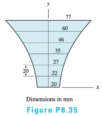
Chapter 8, Problem 8.35P
Use numerical integration to locate the centroid of the symmetric plane
Expert Solution & Answer
Want to see the full answer?
Check out a sample textbook solution
Students have asked these similar questions
The resistance R and load effect S for a given failure mode are statistically independent random variables
with marginal PDF's
1
fR (r) =
0≤r≤100
100'
fs(s)=0.05e-0.05s
(a) Determine the probability of failure by computing the probability content of the failure domain defined
as {r
Please solve this problem as soon as possible My ID# 016948724
The gears shown in the figure have a diametral pitch of 2 teeth per inch and a 20° pressure angle.
The pinion rotates at 1800 rev/min clockwise and transmits 200 hp through the idler pair to gear
5 on shaft c. What forces do gears 3 and 4 transmit to the idler shaft?
TS
I
y
18T
32T
This
a
12
x
18T
C
48T
5
Chapter 8 Solutions
International Edition---engineering Mechanics: Statics 4th Edition
Ch. 8 - Use integration to determine the coordinates of...Ch. 8 - Use integration to determine the coordinates of...Ch. 8 - Use integration to determine the coordinates of...Ch. 8 - Use integration to determine the coordinates of...Ch. 8 - Use integration to determine the coordinates of...Ch. 8 - Use integration to determine the coordinates of...Ch. 8 - Using integration, locate the centroid of the area...Ch. 8 - Determine the y-coordinate of the centroid of the...Ch. 8 - Determine the y-coordinate 0f the centroid of the...Ch. 8 - Use integration to locate the centroid of the...
Ch. 8 - Locate the centroid of the parabola by...Ch. 8 - Use integration to locate the centroid of the...Ch. 8 - The parametric equations of the plane curve known...Ch. 8 - Use the method of composite areas to calculate the...Ch. 8 - Use the method of composite areas to calculate the...Ch. 8 - Use the method of composite areas to calculate the...Ch. 8 - Use the method of composite areas to calculate the...Ch. 8 - Use the method of composite areas to calculate the...Ch. 8 - Use the method of composite areas to calculate the...Ch. 8 - Use the method of composite areas to calculate the...Ch. 8 - Use the method of composite areas to calculate the...Ch. 8 - The plane region is bounded by a semicircle of...Ch. 8 - The centroid of the plane region shown is at C....Ch. 8 - Compute the centroidal coordinates of the L-shaped...Ch. 8 - Find the centroidal coordinates of the plane...Ch. 8 - Using the method of composite areas, find the...Ch. 8 - Given that the centroid of the plane region is at...Ch. 8 - Using the method of composite curves, locate the...Ch. 8 - Using the method of composite curves, locate the...Ch. 8 - Using the method of composite curves, locate the...Ch. 8 - Using the method of composite curves, locate the...Ch. 8 - Using the method of composite curves, locate the...Ch. 8 - Using the method of composite curves, locate the...Ch. 8 - Determine the ratio a/b for which the centroid of...Ch. 8 - Use numerical integration to locate the centroid...Ch. 8 - Determine the centroidal coordinates of the plane...Ch. 8 - Compute the centroidal y-coordinate of the plane...Ch. 8 - The equation of the catenary shown is y = 100 cosh...Ch. 8 - Use integration to locate the centroid of the...Ch. 8 - By integration, find the centroid of the surface...Ch. 8 - Locate the centroid of the volume obtained by...Ch. 8 - Solve Prob. 8.41 assuming that the triangle is...Ch. 8 - Use integration to find the centroidal coordinates...Ch. 8 - Solve Prob. 8.43 assuming that the area is...Ch. 8 - Verify the centroidal z-coordinate of the pyramid...Ch. 8 - Use integration to compute the z-coordinate of the...Ch. 8 - Determine the centroidal z-coordinate of the...Ch. 8 - Prob. 8.48PCh. 8 - Locate the centroid of the volume between the...Ch. 8 - Prob. 8.50PCh. 8 - Prob. 8.51PCh. 8 - By the method of composite volumes, determine the...Ch. 8 - By the method of composite volumes, determine the...Ch. 8 - By the method of composite volumes, determine the...Ch. 8 - By the method of composite volumes, determine the...Ch. 8 - By the method of composite volumes, determine the...Ch. 8 - By the method of composite volumes, determine the...Ch. 8 - Use the method of composite volumes to determine...Ch. 8 - The cylindrical container will have maximum...Ch. 8 - Using the method of composite surfaces, locate the...Ch. 8 - Using the method of composite surfaces, locate the...Ch. 8 - Using the method of composite surfaces, locate the...Ch. 8 - Using the method of composite surfaces, locate the...Ch. 8 - Using the method of composite surfaces, locate the...Ch. 8 - Using the method of composite surfaces, locate the...Ch. 8 - The picture board and its triangular supporting...Ch. 8 - By the method of composite curves, locate the...Ch. 8 - By the method of composite curves, locate the...Ch. 8 - By the method of composite curves, locate the...Ch. 8 - Use numerical integration to find the centroid of...Ch. 8 - Prob. 8.71PCh. 8 - Locate the centroid of the volume generated by...Ch. 8 - Prob. 8.73PCh. 8 - Prob. 8.74PCh. 8 - Prob. 8.75PCh. 8 - A 6-in. diameter hole is drilled in the conical...Ch. 8 - A torus is formed by rotating the circle about the...Ch. 8 - A solid of revolution is formed by rotating the...Ch. 8 - Compute the volume of the spherical cap that is...Ch. 8 - Calculate the surface area of the truncated sphere...Ch. 8 - The rim of a steel V-belt pulley is formed by...Ch. 8 - Determine the volume of the machine part shown.Ch. 8 - A solid is generated by rotating the plane area...Ch. 8 - Prob. 8.84PCh. 8 - Find the surface area of the 90 duct elbow.Ch. 8 - Determine the volume of the concrete arch dam.Ch. 8 - (a) Find the volume of liquid contained in the...Ch. 8 - Compute the surface area of the axi-symmetric...Ch. 8 - The steel cylinder with a cylindrical hole is...Ch. 8 - The hemispherical glass bowl is filled with water....Ch. 8 - What is the ratio L/R for which the uniform wire...Ch. 8 - Small screws are used to fasten a piece of...Ch. 8 - Prob. 8.93PCh. 8 - 3.94 The aluminum cylinder is attached to the...Ch. 8 - Prob. 8.95PCh. 8 - Prob. 8.96PCh. 8 - Prob. 8.97PCh. 8 - Locate the center of gravity of the hammer if the...Ch. 8 - Prob. 8.99PCh. 8 - The cylindrical water tank with R = 10 ft and H =...Ch. 8 - Prob. 8.101PCh. 8 - Five 34-in. diameter holes are to be drilled in a...Ch. 8 - Wind pressure acting on a cylinder can be...Ch. 8 - Prob. 8.104PCh. 8 - The pressure acting on the square plate varies as...Ch. 8 - Prob. 8.106PCh. 8 - Prob. 8.107PCh. 8 - If the intensity of the line loading is...Ch. 8 - Prob. 8.109PCh. 8 - The intensity of the line loading acting on a...Ch. 8 - Determine the resultant force or resultant couple...Ch. 8 - The inside surface of each thin shell carries a...Ch. 8 - Calculate the resultant force caused by the water...Ch. 8 - Determine the resultant force acting on the elbow...Ch. 8 - Determine the smallest distance I) that would...Ch. 8 - Each of the three gates has a constant width 1:...Ch. 8 - The concrete dam shown in cross section holds back...Ch. 8 - A concrete seawater dam is shown in cross section....Ch. 8 - Determine the force F required to pull up the...Ch. 8 - The normal pressure acting on the triangular plate...Ch. 8 - One side of the container has a 03-m square door...Ch. 8 - The 12-ft wide quarter-circular gate AB is hinged...Ch. 8 - The center of gravity of the plane wire figure is...Ch. 8 - The 10-m wide gate restrains water at a depth of 6...Ch. 8 - Find the resultant of the line load shown.Ch. 8 - Prob. 8.126RPCh. 8 - Determine the centroidal coordinates of the volume...Ch. 8 - Prob. 8.128RPCh. 8 - Prob. 8.129RPCh. 8 - Prob. 8.130RPCh. 8 - Using the method of composite areas, find the...Ch. 8 - Find the centroid of the truncated parabolic...Ch. 8 - Prob. 8.133RPCh. 8 - A solid of revolution is formed by rotating the...Ch. 8 - Two hemispherical shells of inner diameter 1 m are...Ch. 8 - Calculate the area of the surface generated when...Ch. 8 - Determine the resultant of the line loading, given...Ch. 8 - Determine the centroidal coordinates of the plane...Ch. 8 - The sheet metal trough has a uniform wall...Ch. 8 - The trough is filled with water (=62.4lb/ft3)....Ch. 8 - The thin-walled cylindrical can with a spherical...Ch. 8 - Find the location of the centroid of the shaded...
Knowledge Booster


Learn more about
Need a deep-dive on the concept behind this application? Look no further. Learn more about this topic, mechanical-engineering and related others by exploring similar questions and additional content below.Similar questions
- Question 1. Draw 3 teeth for the following pinion and gear respectively. The teeth should be drawn near the pressure line so that the teeth from the pinion should mesh those of the gear. Drawing scale (1:1). Either a precise hand drawing or CAD drawing is acceptable. Draw all the trajectories of the involute lines and the circles. Specification: 18tooth pinion and 30tooth gear. Diameter pitch=P=6 teeth /inch. Pressure angle:20°, 1/P for addendum (a) and 1.25/P for dedendum (b). For fillet, c=b-a.arrow_forward5. The figure shows a gear train. There is no friction at the bearings except for the gear tooth forces. The material of the milled gears is steel having a Brinell hardness of 170. The input shaft speed (n2) is 800 rpm. The face width and the contact angle for all gears are 1 in and 20° respectively. In this gear set, the endurance limit (Se) is 15 kpsi and nd (design factor) is 2. (a) Find the revolution speed of gear 5. (b) Determine whether each gear satisfies the design factor of 2.0 for bending fatigue. (c) Determine whether each gear satisfies the design factor of 2.0 for surface fatigue (contact stress). (d) According to the computation results of the questions (b) and (c), explain the possible failure mechanisms for each gear. N4=28 800rpm N₁=43 N5=34 N₂=14 P(diameteral pitch)=8 for all gears Coupled to 2.5hp motorarrow_forward1. The rotating steel shaft is simply supported by bearings at points of B and C, and is driven by a spur gear at D, which has a 6-in pitch diameter. The force F from the drive gear acts at a pressure angle of 20°. The shaft transmits a torque to point A of TA =3000 lbĘ in. The shaft is machined from steel with Sy=60kpsi and Sut=80 kpsi. (1) Draw a shear force diagram and a bending moment diagram by F. According to your analysis, where is the point of interest to evaluate the safety factor among A, B, C, and D? Describe the reason. (Hint: To find F, the torque Tд is generated by the tangential force of F (i.e. Ftangential-Fcos20°) When n=2.5, K=1.8, and K₁ =1.3, determine the diameter of the shaft based on (2) static analysis using DE theory (note that fatigue stress concentration factors need to be used for this question because the loading condition is fatigue) and (3) a fatigue analysis using modified Goodman. Note) A standard diameter is not required for the questions. 10 in Darrow_forward
- 3 N2=28 P(diametral pitch)=8 for all gears Coupled to 25 hp motor N3=34 Full depth spur gears with pressure angle=20° N₂=2000 rpm (1) Compute the circular pitch, the center-to-center distance, and base circle radii. (2) Draw the free body diagram of gear 3 and show all the forces and the torque. (3) In mounting gears, the center-to-center distance was reduced by 0.1 inch. Calculate the new values of center-to-center distance, pressure angle, base circle radii, and pitch circle diameters. (4)What is the new tangential and radial forces for gear 3? (5) Under the new center to center distance, is the contact ratio (mc) increasing or decreasing?arrow_forward2. A flat belt drive consists of two 4-ft diameter cast-iron pulleys spaced 16 ft apart. A power of 60 hp is transmitted by a pulley whose speed is 380 rev/min. Use a service factor (Ks) pf 1.1 and a design factor 1.0. The width of the polyamide A-3 belt is 6 in. Use CD=1. Answer the following questions. (1) What is the total length of the belt according to the given geometry? (2) Find the centrifugal force (Fc) applied to the belt. (3) What is the transmitted torque through the pulley system given 60hp? (4) Using the allowable tension, find the force (F₁) on the tight side. What is the tension at the loose side (F2) and the initial tension (F.)? (5) Using the forces, estimate the developed friction coefficient (f) (6) Based on the forces and the given rotational speed, rate the pulley set. In other words, what is the horse power that can be transmitted by the pulley system? (7) To reduce the applied tension on the tight side, the friction coefficient is increased to 0.75. Find out the…arrow_forwardThe tooth numbers for the gear train illustrated are N₂ = 24, N3 = 18, №4 = 30, №6 = 36, and N₁ = 54. Gear 7 is fixed. If shaft b is turned through 5 revolutions, how many turns will shaft a make? a 5 [6] barrow_forward
- Please do not use any AI tools to solve this question. I need a fully manual, step-by-step solution with clear explanations, as if it were done by a human tutor. No AI-generated responses, please.arrow_forwardPlease do not use any AI tools to solve this question. I need a fully manual, step-by-step solution with clear explanations, as if it were done by a human tutor. No AI-generated responses, please.arrow_forwardCE-112 please solve this problem step by step and give me the correct answerarrow_forward
arrow_back_ios
SEE MORE QUESTIONS
arrow_forward_ios
Recommended textbooks for you
 International Edition---engineering Mechanics: St...Mechanical EngineeringISBN:9781305501607Author:Andrew Pytel And Jaan KiusalaasPublisher:CENGAGE L
International Edition---engineering Mechanics: St...
Mechanical Engineering
ISBN:9781305501607
Author:Andrew Pytel And Jaan Kiusalaas
Publisher:CENGAGE L
Mechanical Engineering: Centroids & Center of Gravity (1 of 35) What is Center of Gravity?; Author: Michel van Biezen;https://www.youtube.com/watch?v=Tkyk-G1rDQg;License: Standard Youtube License