Concept explainers
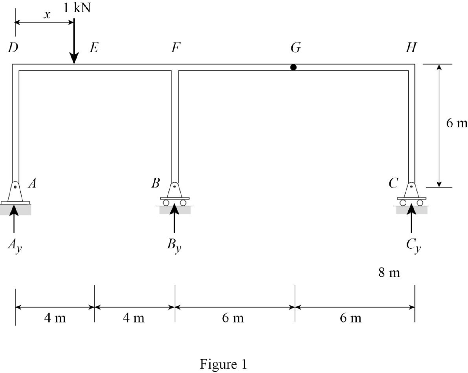
Draw the influence lines for the vertical reactions at supports A, B, C and the shear and bending moment at point E.
Explanation of Solution
Calculation:
Apply a 1 kN unit moving load at a distance of x from left end D.
Sketch the free body diagram of frame as shown in Figure 1.
Influence line for vertical reaction at supports C.
Refer Figure 1.
Find the equation of vertical reaction at supports C.
Apply 1 kN load just left of G
Consider section GH.
Take moment at G from C.
Consider clockwise moment as positive and anticlockwise moment as negative.
Apply 1 kN load just right of G
Consider section GH.
Take moment at G from C.
Consider clockwise moment as positive and anticlockwise moment as negative.
Thus, the equation of vertical reaction at supports C as follows,
Find the influence line ordinate of
Substitute 20 m for
Thus, the influence line ordinate of
Similarly calculate the influence line ordinate of
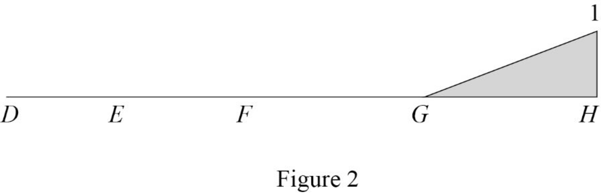
| x (m) | Points | Influence line ordinate of |
| 0 | D | 0 |
| 4 | E | 0 |
| 8 | F | 0 |
| 14 | G | 0 |
| 20 | H | 1 |
Sketch the influence line diagram for vertical reaction at supports C using Table 1 as shown in Figure 2.
Influence line for vertical reaction at support A.
Apply 1 kN load just left of F
Refer Figure 1.
Find the equation of vertical reaction at supports C.
Consider section DF.
Take moment at B from A.
Consider clockwise moment as positive and anticlockwise moment as negative.
Apply 1 kN load just right of F.
Consider section FH.
Consider moment at B from A is equal to from C.
Consider clockwise moment as positive and anticlockwise moment as negative.
Find the equation of vertical reaction at A from F to G
Substitute 0 for
Find the equation of vertical reaction at A from G to H
Substitute
Thus, the equation of vertical reaction at supports A as follows,
Find the influence line ordinate of
Substitute 14 m for
Thus, the influence line ordinate of
Similarly calculate the influence line ordinate of
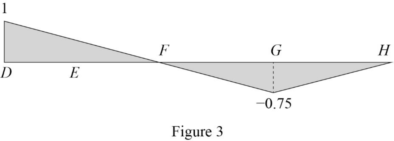
| x (m) | Points | Influence line ordinate of |
| 0 | D | 1 |
| 4 | E | 0.5 |
| 8 | F | 0 |
| 14 | G | |
| 20 | H | 0 |
Sketch the influence line diagram for the vertical reaction at support A using Table 2 as shown in Figure 3.
Influence line for vertical reaction at support B.
Apply a 1 kN unit moving load at a distance of x from left end C.
Refer Figure 1.
Apply vertical equilibrium in the system.
Consider upward force as positive and downward force as negative.
Find the equation of vertical support reaction
Substitute
Find the equation of vertical support reaction
Substitute
Thus, the equation of vertical support reaction at B as follows,
Find the influence line ordinate of
Substitute 8 m for
Thus, the influence line ordinate of
Similarly calculate the influence line ordinate of
| x (m) | Points | Influence line ordinate of |
| 0 | D | 0 |
| 4 | E | 0.5 |
| 8 | F | 1 |
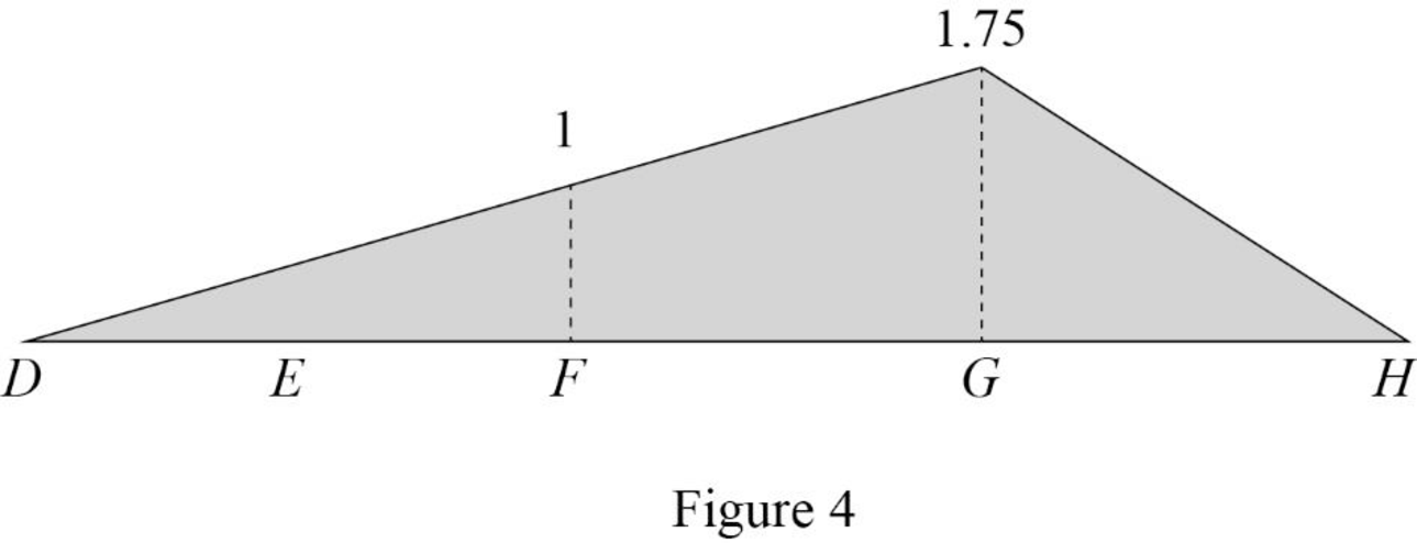
| 14 | G | 1.75 |
| 20 | H | 0 |
Sketch the influence line diagram for the vertical reaction at support B using Table 3 as shown in Figure 4.
Influence line for shear at point E.
Find the equation of shear
Apply 1 kN just left of E.
Consider section DE.
Sketch the free body diagram of the section AD as shown in Figure 5.
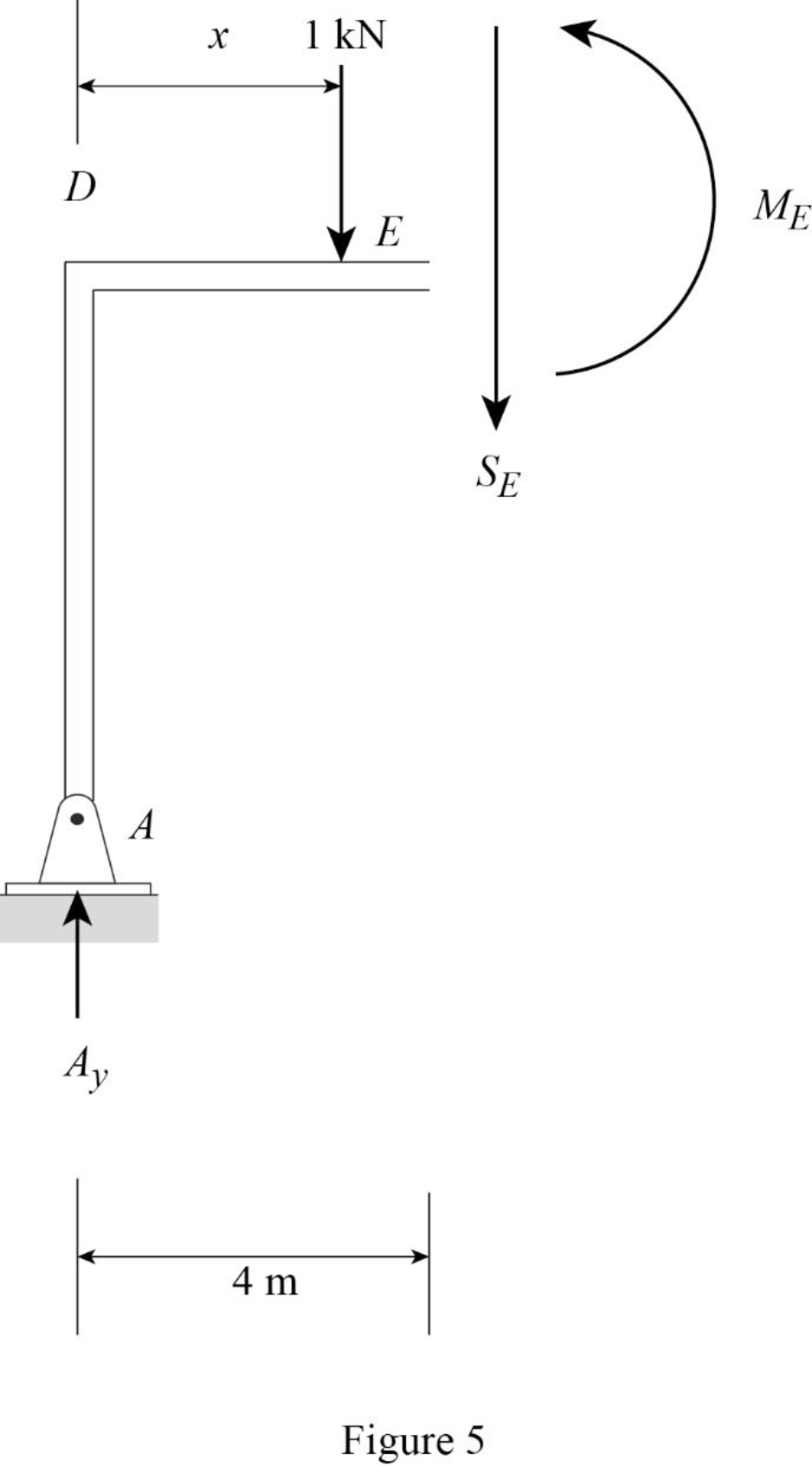
Refer Figure 5.
Apply equilibrium equation of forces.
Consider upward force as positive
Find the equation of shear force at E of portion DE
Substitute
Find the equation of shear
Apply 1 kN just right of E.
Consider section DE.
Sketch the free body diagram of the section DE as shown in Figure 6.
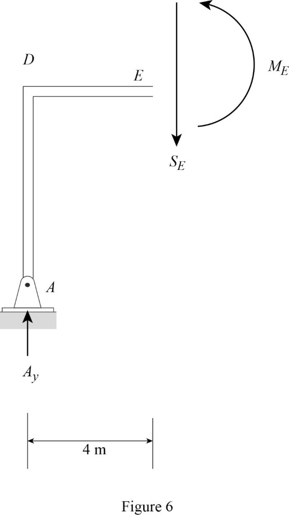
Refer Figure 6.
Apply equilibrium equation of forces.
Consider upward force as positive
Find the equation of shear force at E of portion EG
Substitute
Find the equation of shear force at E of portion GH
Substitute
Thus, the equations of the influence line for
Find the influence line ordinate of
Substitute 4 m for
Thus, the influence line ordinate of
Find the shear force of
| x (m) | Points | Influence line ordinate of |
| 0 | D | 0 |
| 4 | ||
| 4 | ||
| 8 | F | 0 |
| 14 | G | |
| 20 | H | 0 |
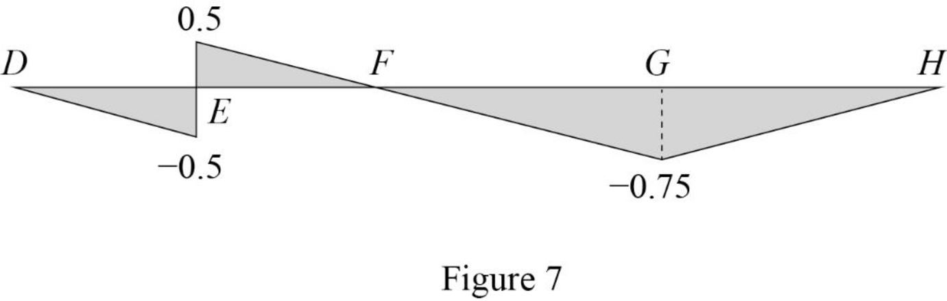
Draw the influence lines for the shear force at point E using Table 4 as shown in Figure 7.
Influence line for moment at point E.
Refer Figure 5.
Consider section DE.
Consider clockwise moment as positive and anticlockwise moment as negative.
Take moment at E.
Find the equation of moment at E of portion DE
Substitute
Refer Figure 6.
Consider section DE.
Find the equation of moment at E of portion EH
Consider clockwise moment as positive and anticlockwise moment as negative.
Take moment at E.
Find the equation of moment at E of portion EF.
Find the equation of moment at E of portion EG
Substitute
Find the equation of moment at E of portion GH
Substitute
Thus, the equations of the influence line for
Find the influence line ordinate of
Substitute 4 m for
Thus, the influence line ordinate of
Find the moment at various points of x using the Equations (15), (16), and (17) and summarize the value as in Table 5.
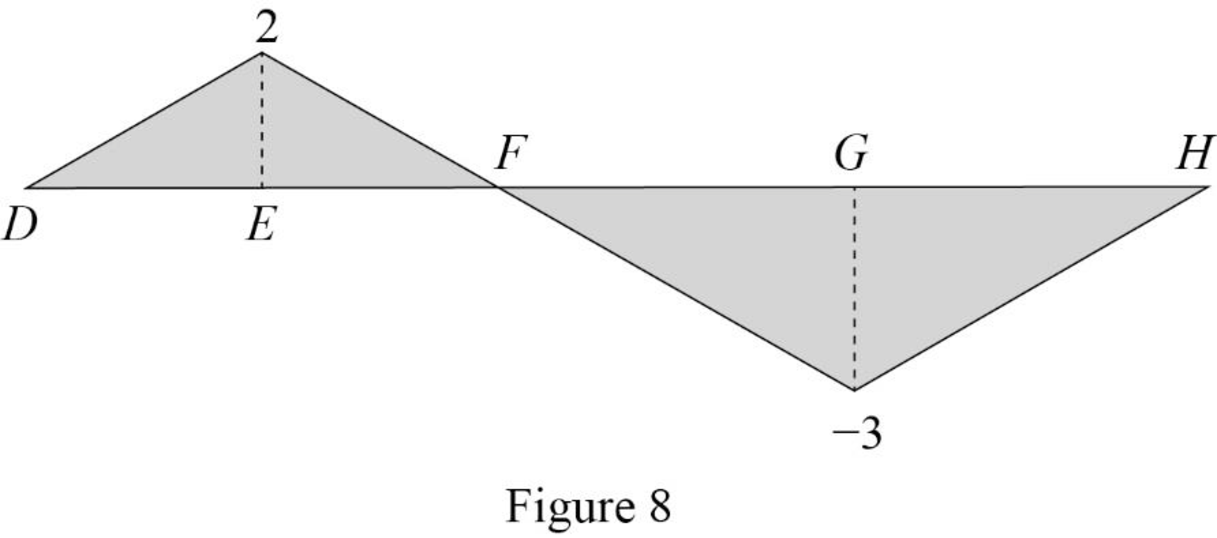
| x (m) | Points | Influence line ordinate of |
| 0 | D | 0 |
| 4 | E | 2 |
| 8 | F | 0 |
| 14 | G | |
| 20 | H | 0 |
Draw the influence lines for the moment at point E using Table 5 as shown in Figure 8.
Therefore, the influence lines for the vertical reactions at supports A, B, and C and the influence lines for the shear and bending moment at point E are drawn.
Want to see more full solutions like this?
Chapter 8 Solutions
Structural Analysis, Si Edition


- Consider a pool of saturated water at atmospheric pressure. The base of the pool is made of thick polished copper square plate of length 1 m. To generate steam, exhaust gas is flowing underneath and parallel to the base plate with velocity 3 m/s and average temperate of 1090°C. The bottom surface the plate is at constant temperature of 110°. Use the properties of air for exhaust gas. a) Determine the boiling heat transfer rate. b) Determine the temperature of the top surface of the plate. Comment on the results. c) Examine the impact of your assumptions on your solutions. (what will change if any of the assumptions is not valid?)arrow_forward-The axial deflection pipe in inches. -The lateral deflection of the beam in inches -The total deflection of the beam like structure in inches ? all to 4 sig figs AI did not help. as i input what i get im not sure if its a rounding error or what.arrow_forward1. For the foundation shown below: Qapp = 60 kips (Load obtained from structural engineer) 1.5 ft G.W.T. 3 ft Poorly Graded Sand (SP): Ym 115 pcf (above G.W.T.) Ysat 125 pcf (below G.W.T.) c' = 0, ' = 35° K Square footing, 4' x 4' Foundation Dimension Information: 1-ft x 1-ft square concrete column. 1-ft thick "foot" flanges. Yconc=150 pcf *Assume weight of reinforcing steel included in unit weight of concrete. *Assume compacted backfill weighs the same as in-situ soil. Assume this foundation is being designed for a warehouse that had a thorough preliminary soil exploration. Using the general bearing capacity equation: a. Calculate the gross applied bearing pressure, the gross ultimate bearing pressure, and determine if the foundation system is safe using a gross bearing capacity ASD approach. Please include the weight of the foundation, the weight of the backfill soil, and the effect of the uplift pressure caused by the presence of the water table in your bearing capacity…arrow_forward
- ٢٥ ٠٥:٤٠١٠ 2025 ChatGPT VivaCut Onet Puzzle مسلم X Excel JPG I❤> PDF Copilot Chat Bot PDF2IMG iLovePDF NokoPrint O.O StudyX ☑ W CapCut Candy Crush DeepSeek Word ☐ Saga 啡 AcadAl ل TikTokarrow_forwardRefer to the figure below. Given: L = 7 m, y = 16.7 kN/m², and ø' = 30°. L L3 ση Sand γ $' D T LA L σε σε IN P Sand 1. Calculate the theoretical depth of penetration, D. (Enter your answer to three significant figures.) D= m 2. Calculate the maximum moment. (Enter your answer to three significant figures.) Mmax kN-m/marrow_forwardWhy is it important for construction project managers to be flexible when dealing with the many variable factors that pop up in a project?arrow_forward
