
Concept explainers
Videos
Referto Figure 8-2. Replace the values shown with the following. Solvefor all theunknownvalues.
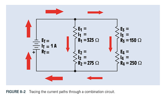
Solve for the unknown values in the figure.
Answer to Problem 1RQ
| ET = 264.47 V | E1 = 149.87 V | E2 = 114.79 V | E3 = 143.48 V | E4 = 120.98 V |
| IT = 0.6 A | I1 = 0.3186 A | I2 = 0.3186 A | I3 = 0.2813 A | I4 = 0.2813 A |
| RT = 440.79 Ω | R1 = 470 Ω | R2 = 360 Ω | R3 = 150 Ω | R4 = 250Ω |
Explanation of Solution
The circuit diagram is redrawn with given data;
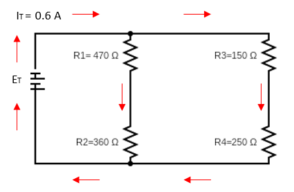
Description:
For the given combination circuit, total resistance will be series combination of R1 and R2 in parallel combination with series combination of R3 and R4. Calculations are shown below,
Using the current IT and resistance RT, we calculate the voltage ET
The individual voltage drops can be calculated using the voltage divider rule.
Since R1 and R2 are series connected, the same current flows through them. Hence, I1=I2
Similarly, R3 and R4 are series connected, therefore I3=I4
Conclusion:
The unknown values have been calculated using rules for combination circuit and ohm’s law.
Want to see more full solutions like this?
Chapter 8 Solutions
Delmar's Standard Textbook of Electricity (MindTap Course List)


- During the lab you will design and measure a differential amplifier, made with an opamp. inside generator R5 ww 500 V1 0.1Vpk 1kHz 0° R6 w 50Ω R1 ww 10ΚΩ VCC C1 balanced wire R3 w 15.0V signal+ 100nF U1A TL082CP ground 2 signal- R4 w C2 Question5: Calculate R3 and R4 for a 20dB. 100nF VEE -15.0V R2 ww 10ΚΩarrow_forwardnot use ai pleasearrow_forward3. Consider the system described by the transfer function Gp(s) polynomial controller to satisfy the below specifications: 1) The settling time is t = 1 second, 2) 0.1% peak overshoot, 3) and zero steady-state error for a ramp input. The sampling period is T = 0.01 second. 1 = Design a discrete-time s(s+5)*arrow_forward
- Problem 2 Does there exist a value a that makes the two systems S₁ and S₂ equal? If so, what is this value ? If not, explain why. S₁ x[n] x[n] D D -2 → host 回洄 S with h[m] " 999. усиз -1012345 harrow_forwardplease not use any aiarrow_forwardProblem 2 Does there exist a value a that makes the two systems S₁ and S₂ equal? If so, what is this value ? If not, explain why. S₁ x[n] x[n] D D -2 → host 回洄 S with h[m] " 999. усиз -1012345 harrow_forward
- Solve only no 8, Don't use chatgpt or any , only expertarrow_forwardI need help in creating a matlab code to find the currents USING MARTIXS AND INVERSE to find the currentarrow_forwardQuestion 2 A transistor is used as a switch and the waveforms are shown in Figure 2. The parameters are Vcc = 225 V, VBE(sat) = 3 V, IB = 8 A, VCE(sat) = 2 V, Ics = 90 A, td = 0.5 µs, tr = 1 µs, ts = 3 µs, tƒ = 2 μs, and f 10 kHz. The duty cycle is k 50%. The collector- emitter leakage current is ICEO = 2 mA. Determine the power loss due to the collector current: = = = (a) during turn-on ton = td + tr VCE Vcc (b) during conduction period tn V CE(sat) 0 toff" ton Ics 0.9 Ics (c) during turn-off toff = ts + tf (d) during off-time tot (e) the total average power losses PT ICEO 0 IBS 0 Figure 2 V BE(sat) 0 主 * td tr In Is If to iB VBE T= 1/fsarrow_forward
- Question 1: The beta (B) of the bipolar transistor shown in Figure 1 varies from 12 to 60. The load resistance is Rc = 5. The dc supply voltage is VCC = 40 V and the input voltage to the base circuit is VB = 5 V. If VCE(sat) = 1.2 V, VBE(sat) = 1.6 V, and RB = 0.8 2, calculate: (a) the overdrive factor ODF. (b) the forced ẞ (c) the power loss in the transistor PT. IB VB RB + V BE RC Vcc' Ic + IE Figure 1 VCEarrow_forwardI need help in creating a matlab code to find the currentsarrow_forwardI need help fixing this MATLAB code: as I try to get it working there were some problems:arrow_forward
 Introductory Circuit Analysis (13th Edition)Electrical EngineeringISBN:9780133923605Author:Robert L. BoylestadPublisher:PEARSON
 Delmar's Standard Textbook Of ElectricityElectrical EngineeringISBN:9781337900348Author:Stephen L. HermanPublisher:Cengage Learning
 Programmable Logic ControllersElectrical EngineeringISBN:9780073373843Author:Frank D. PetruzellaPublisher:McGraw-Hill Education
 Fundamentals of Electric CircuitsElectrical EngineeringISBN:9780078028229Author:Charles K Alexander, Matthew SadikuPublisher:McGraw-Hill Education
 Electric Circuits. (11th Edition)Electrical EngineeringISBN:9780134746968Author:James W. Nilsson, Susan RiedelPublisher:PEARSON
 Engineering ElectromagneticsElectrical EngineeringISBN:9780078028151Author:Hayt, William H. (william Hart), Jr, BUCK, John A.Publisher:Mcgraw-hill Education,