
Delmar's Standard Textbook of Electricity (MindTap Course List)
6th Edition
ISBN: 9781285852706
Author: Stephen L. Herman
Publisher: Cengage Learning
expand_more
expand_more
format_list_bulleted
Concept explainers
Videos
Textbook Question
Chapter 7, Problem 8PP
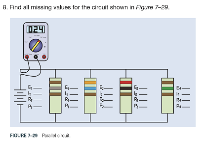
Find all missing values for the circuit shown in Figure 7-29.
Expert Solution & Answer

Trending nowThis is a popular solution!

Students have asked these similar questions
EXAMPLE 6.3
Suppose the Fourier transform of a pulse is as follows:
(1-a)
Ть.
2Ть
H(f) = <
α
(To) (-Tof+
1 +a
(1-a)
(1+α)
·<|f|≤·
2
2ть
2Ть
(1+α)
0,
<\f\
2Ть
where 0≤a≤1. Show that this pulse in both time and frequency domains satisfies the Nyquist
criterion.
In matlab
not use ai please
Chapter 7 Solutions
Delmar's Standard Textbook of Electricity (MindTap Course List)
Ch. 7 - What characterizes a parallel circuit?Ch. 7 - Why are circuits in homes connected in parallel?Ch. 7 - State three rules concerning parallel circuits.Ch. 7 - A parallel circuit contains four branches. One...Ch. 7 - Four resistors having a value of 100 each are...Ch. 7 - A parallel circuit has three branches. An ammeter...Ch. 7 - Four resistors having values of 270,330,510, and...Ch. 7 - A parallel circuit contains four resistors. The...Ch. 7 - A circuit contains a 1200-, a 2200-, and a 3300-...Ch. 7 - You have been hired by a homeowner to install a...
Ch. 7 - You are employed in a large industrial plant. A...Ch. 7 - You are an electrician. You have been asked by a...Ch. 7 - A car lot uses incandescent lamps to supply...Ch. 7 - Using the three rules for parallel circuits and...Ch. 7 - Using the three rules for parallel circuits and...Ch. 7 - Using the rules for parallel circuits and Ohmslaw,...Ch. 7 - Using the rules for parallel circuits and Ohmslaw,...Ch. 7 - A parallel circuit contains the following resistor...Ch. 7 - A parallel Circuit contains the following resistor...Ch. 7 - Find all missing values for the Circuit shown in...Ch. 7 - Find all missing values for the circuit shown in...
Knowledge Booster


Learn more about
Need a deep-dive on the concept behind this application? Look no further. Learn more about this topic, electrical-engineering and related others by exploring similar questions and additional content below.Similar questions
- In matlabarrow_forwardEXAMPLE 4.4 In a binary symmetric communication (BSC) channel, the input bits transmitted over the channel are either 0 or 1 with probabilities p and 1-p, respectively. Due to channel noise, errors are made. As shown in Figure 4.4, the channel is assumed to be symmetric, which means the probability of receiving 1 when 0 is transmitted is the same as the probability of receiving 0 when 1 is transmit- ted. The conditional probabilities of error are assumed to be each e. Determine the average prob- ability of error, also known as the bit error rate, as well as the a posteriori probabilities.arrow_forwardWhat is the bandwidth requirement in Hz for baseband binary transmission at 64 kbps, if the roll-off factor is 0.25?arrow_forward
- EXAMPLE 6.4 Suppose the roll-off factor is 25% and the bandwidth of a baseband transmission system satisfying the Nyquist criterion is 30 kHz. Determine the bit rate. Solution 1+α 1arrow_forwardEXAMPLE 4.9 In a communication system, the noise level is modeled as a Gaussian random variable with m=0 and ² = 0.0001. Determine P(X > 0.01) and P(-0.04 ≤x≤ 0.05). 3arrow_forwardSuppose the random variable X is uniformly distributed between 0 and 1 with probability 0.25, takes on the value of 1 with probability p, and is uniformly distributed between 1 and 2 with probability 0.5. Determine p as well as the pdf and cdf of the random variable Xarrow_forward
- constants: A (medium) single phase transmission line 100 km long has the following Resistance/km = 0.25 2; Susceptance/km = 14 × 10 siemen; Reactance/km = 0.8 Receiving end line voltage = 66,000 V Assuming that the total capacitance of the line is localised at the receiving end alone, determine (i) the sending end current (ii) the sending end voltage (iii) regulation and (iv) supply power factor. The line is delivering 15,000 kW at 0.8 power factor lagging. Draw the phasor diagram to illustrate your calculations.arrow_forwardFor the power system given below, the voltage at bus 2 is kept at 1.03 pu. The maximum power can be delivered by G2 is 35 MW. Obtain the load flow solution. Take the base power 100 MVA. V₁ = 1.0520 G₁ 0.02+j0.06 G2 V2=1.03 P2 = 35 MW 0.08+j0.24 SL2 20+j50 MVA SL3 60+j25 MVA 0.06+j0.018arrow_forwardGeneral Directions: Read the questions carefully and answer (3*10=30marks) 1. Design a summing amplifier by choosing appropriate values of resistors an so that the output is 5 times the sum of the input voltages. (you are free to use any number of inputs, the type of op-amp, any value of resistors) 2. Derive the equation for the closed loop gain of the inverting and non-inverting Amplifier using appropriate circuit diagrams. 3. Determine the values read by the measuring devices using appropriate formulae www Voc +8V R₁ 33 k Rc 2.2 k ww WWW Poc 200 R₁₂ RE 10 kn 1.0 knarrow_forward
- 十 : + B 日 العنوان I need a detailed drawing with explanation ややハメPV+96252 4 Project Homework: Create a simulation for a tank when the flowrate inside and outside the tank must range between 0 and 10 lit/s: 1) The level should be controlled within a range between more than zero to 1000 lit. 2) An alarm must be launched when the level is out of range (less than 100 and more than 900 lit). 3) When the capacity reaches to the maximum the motor turns OFF. area=A Qout -20 solve in lab view X9.01 *175*1arrow_forwardProject Homework: Create a simulation for a tank when the flowrate inside and outside the tank must range between 0 and 10 lit/s: 1) The level should be controlled within a range between more than zero to 1000 lit. 2) An alarm must be launched when the level is out of range (less than 100 and more than 900 lit). 3) When the capacity reaches to the maximum the motor turns OFF. Qin h C Qout area=A solve in lab viewarrow_forwardQUESTION [3] A no-load and short-circuit test should be conducted on a 220V/110V, 280VA transformer. a. Draw the circuit diagram for the no-load test and include all measurements that should be made. Also write down the maximum voltage that you should apply to the primary winding and estimate the current drawn from the supply. (5) b. Draw a circuit diagram for the short-circuit test and include all measurements that should be made. Also write down the maximum current that should be allowed to flow in the primary winding and estimated the primary voltage that will cause this value of the current to flow. (5)arrow_forward
arrow_back_ios
SEE MORE QUESTIONS
arrow_forward_ios
Recommended textbooks for you
 Delmar's Standard Textbook Of ElectricityElectrical EngineeringISBN:9781337900348Author:Stephen L. HermanPublisher:Cengage Learning
 Electricity for Refrigeration, Heating, and Air C...Mechanical EngineeringISBN:9781337399128Author:Russell E. SmithPublisher:Cengage Learning
 EBK ELECTRICAL WIRING RESIDENTIALElectrical EngineeringISBN:9781337516549Author:SimmonsPublisher:CENGAGE LEARNING - CONSIGNMENT
 Power System Analysis and Design (MindTap Course ...Electrical EngineeringISBN:9781305632134Author:J. Duncan Glover, Thomas Overbye, Mulukutla S. SarmaPublisher:Cengage Learning
Delmar's Standard Textbook Of Electricity
Electrical Engineering
ISBN:9781337900348
Author:Stephen L. Herman
Publisher:Cengage Learning
Electricity for Refrigeration, Heating, and Air C...
Mechanical Engineering
ISBN:9781337399128
Author:Russell E. Smith
Publisher:Cengage Learning
EBK ELECTRICAL WIRING RESIDENTIAL
Electrical Engineering
ISBN:9781337516549
Author:Simmons
Publisher:CENGAGE LEARNING - CONSIGNMENT
Power System Analysis and Design (MindTap Course ...
Electrical Engineering
ISBN:9781305632134
Author:J. Duncan Glover, Thomas Overbye, Mulukutla S. Sarma
Publisher:Cengage Learning
Current Divider Rule; Author: Neso Academy;https://www.youtube.com/watch?v=hRU1mKWUehY;License: Standard YouTube License, CC-BY