Concept explainers
|
|
|
|
|
|
||||
|
|
|
|
|
|
||||
|
|
|
|
|
|
||||
|
|
|
|
|
|
||||
|
|
|
|
|
|
||||
|
|
|
|
|
|
||||
|
|
|
|
|
|
||||
|
|
|
|
|
|
||||

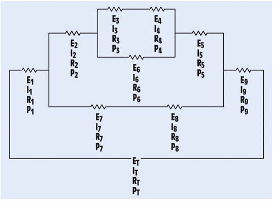
FIGURE 8-26 A combination circuit.
The unknown values in the circuit.
Answer
| ET = 24.04 V | E1 = 3.4V | E2 = 4.8 V | E3 = 0.478 V | E4 = 1.248 V |
| IT = 24.02mA | I1 = 24.02mA | I2 = 9.614 mA | I3 = 3.854 mA | I4 = 3.854 mA |
| RT = 942 Ω | R1 = 144 Ω | R2 = 499 Ω | R3 = 124Ω | R4 = 324 Ω |
| PT = 0.576 W | P1 = 0.0806W | P2 = 0.0461W | P3 = 0.00184W | P4 = 0.00481W |
| E5 = 2.11 V | E6 = 1.726V | E7 = 3.6 V | E8 = 5.04V | E9 = 12 V |
| I5 = 9.614 mA | I6 = 5.76 mA | I7 = 14.41 mA | I8 = 14.41 mA | I9 = 24.02 mA |
| R5 = 220 Ω | R6 = 300Ω | R7 = 86Ω | R8 = 360Ω | R9 = 500 Ω |
| P5 = 0.0203 W | P6 = 0.00995 W | P7 = 0.0518W | P8 = 0.0726W | P9 = 0.288 W |
Explanation of Solution

In the given question,
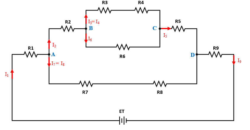
Current flowing through R1 is denoted by I1
Current flowing through R2is denoted by I2
Current flowing through R3 and R4 is denoted by I3(= I4)
Current flowing through R5 is denoted by I5
Current flowing through R6 is denoted by I6
Current flowing through R7 and R8 is denoted by I7 (= I8)
Current flowing through R9is denoted by I9
The total power consumed by the circuit is equal to sum of power consumed by individual resistors. Hence,
Using the voltage E4 and Power P4, we calculate resistance R4 and current I4
Since R3 and R4 are in series, the same current flows through both. Therefore, I3=I4=3.854 mA
Using the current I3 and resistance R3 find the voltage E3
Since R6 is in parallel with series combination of R3 and R4. Hence,
E6= 0.478 + 1.248 =1.726 V
Using the voltage E6 and Power P6, we calculate resistance R6 and current I6
At node B,
Using P2 and I2, we calculate R2
Using P2 and I2, we calculate E2
Since the incoming current in a network is equal to the outgoing current, current at node B= current at node C: I2=I5=9.614 mA
Using the voltage E5 and Power P5, we calculate resistance R5 and current I5
The total voltage drop across R7 and R8 i.e. E7 and E8 will be
The total power consumed in the branch containing resistors R7 and R8 will be 0.0518+0.0726 = 0.1244 W
Using the total power consumed and the total voltage, we can compute the total current in the network of R7 and R8.
Using the voltage and Power, we calculate R7, R8 and current I7, I8
At node A,
Since the incoming current in a network is equal to the outgoing current, current at node A=current at node D: I1 = I9 =IT=24.02 mA
Using the current I1 and Power P1, we calculate resistance R1 and voltage E1
Using the current I9 and Power P9, we calculate resistance R9 and voltage E9
Total voltage applied across the network will be,
Want to see more full solutions like this?
- Q3. Answer the following questions T 1. Compared to the bipolar voltage-switching scheme, the unipolar scheme is "effectively" doubling the switching frequency. Explain the statement's meaning and how this effect can be generated. 2. What are the properties of a good power switch, and what are its basic ratings? 3. What are the objectives of any PWM strategy for three-phase inverters? 4. Why is the current control PWM rectifier in the dq rotating reference frame preferred over the abc reference frame? 5. Define the switch utilization factor. Show how this factor can be calculated for different single-phase inverters for square wave operation mode at the maximum rated output.arrow_forwardQ1.B. Explain output control by voltage cancellation in a single-phase inverter. What are the advantages over square wave operation?arrow_forwardQ3.B. What is the problem of three-phase HW rectifier and how can be resolved?arrow_forward
- Q3-consider the unity feedback system shown below: a.Evaluate general formula of ess? b.Calculate the steady state error of the closed loop system due to R(s) unit step input, D(s)=0]? c.Calculate the steady-state response when D(s) and ramp and R(s)=0?arrow_forward- = 400KHZ. Q1. In a Boost converter, L = 25 μH, Vin = 12 V, D = 0.4, P = 25 W, and fs (i) if the output load is changing. Calculate the critical value of the output load P,below which the converter will enter the discontinuous conduction mode of operation. Assume the total turn-on loss is equal to 2 W. (ii) Assuming the input voltage fluctuates from 10 V to 14 V and the output voltage is regulated to 20 V. Calculate the critical value of the inductance L below which this Boost converter will enter the discontinuous conduction mode of operation at P = 5 W. (iii) Draw the waveforms for inductor voltage, inductor current, and the capacitor current for this Boost converter at the output load that causes it to operate at the border of continuous and discontinuous modes. vd tow 77 N₂ AT 22 1-1arrow_forwardDon't use ai to answer I will report you answerarrow_forward
- Answer the following questions: 1- Write radiation resistance (R.) equation for infinitesimal dipole antenna. 2- Write the angle expression form of first null beam width (FNBW) for 2/2 dipole. 3- Define the Directivity of antenna. 4- Write radar cross section equation. 5- Write the input impedance (Z) expression of lossless transmission line.arrow_forwardThe input reactance of an infinitesimal linear dipole of length 1/60 and radius a = x/200 is given by [In(/2a) - 11 X-120- tan(kl/2) Assuming the wire of the dipole is copper with a conductivity of 5.7 × 10'S/m. determine at f = 1 GHz the (a) loss resistance (b) radiation resistance (c) radiation efficiency input impedancearrow_forwardQ4- a) For the block diagram of control system shown below with its unit step response. Determine (K, a,damping ration, Maximum overshoot, Wn, Wd,ẞ, ts, tp, td, tr, and overall transfer function? C(1) ↑ 1.4 1.2 1 0.8 0.6 0.4 0.2 R(s) E(s) K C(s) $(s + α) 0.05 0.1 0.15 0.2 +2% -2%arrow_forward
- Determine the power radiated for the antenna has the following specifications (48 ohm radiation resistance, 2 ohm loss resistance and 50 ohms reactance) connected to generator with 12 V open circuit and internal impedance 50 ohm via à long transmission line with 100 ohm characteristic impedance.arrow_forwardDon't use ai to answer I will report you answerarrow_forwardDon't use ai to answer I will report you answerarrow_forward
 Delmar's Standard Textbook Of ElectricityElectrical EngineeringISBN:9781337900348Author:Stephen L. HermanPublisher:Cengage Learning

