Effect on cycle length due to
Answer to Problem 18P
Cycle length value increases with
Explanation of Solution
Given data:
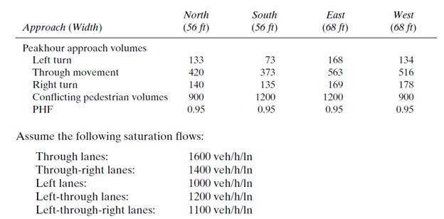
Calculation:
Evaluating equivalent hourly flow −
Similarly, evaluating equivalent hourly flow for all traffic movements −
Table 1
| Approach (width) | N (56ft) | S (56ft) | E (68ft) | W (68ft) |
| Left turn | 133/0.95 = 140 | 73/0.95 = 77 | 168/0.95 = 177 | 134/0.95 = 142 |
| Through movement | 443 | 393 | 593 | 544 |
| Right turn | 148 | 143 | 178 | 188 |
| Conflicting pedestrian volume | 948 | 1264 | 1264 | 948 |
Assuming lane configuration as one dedicated left turn and combined through and right lane −
Table 2
| Approach | N | S | E | W |
| Left | 140 | 77 | 177 | 142 |
| Through + Right | 589 (442+147) | 535 (393+178) | 771 (593+178) | 730 (543+187) |
Assume a phase scheme and find critical ratios(
Table 3
| - | Phase lE-W (Left) | Phase llE-W (Through) | Phase lllN-S (Left) | Phase lVN-S (Through) |
| 177 | 771 | 140 | 589 | |
| 1000 | 3000 (1600+1400) | 1000 | 3000 (1600+1400) | |
| 0.177 | 0.257 | 0.140 | 0.196 |
Sum of critical ratios −
Assuming lost time per phase (
So, Total lost time −
Now, determining the optimum cycle length −
(Cycle lengths are generally multiple of
Finding Total effective green time −
Effective time for phase
For Phase l
(Assuming yellow time as
For Phase ll
For Phase lll
For Phase lV
Table 4
| Phase | Allocated green & yellow time (in sec) |
Total cycle length
Green time required for pedestrian crossing can be calculated as following formula:
(Assuming the crosswalk width as
Where,
Calculating
Calculating minimum time required (
Minimum time required for N approach (
Minimum time required for S approach (
Minimum time required for E approach (
Minimum time required for W approach (
Table 5
| Phase | Minimum green time (in sec) |
Sum of green and yellow time is given by,
Total cycle length is given by,
Now increasing the pedestrian volume with
Table 6
| New conflicting pedestrian volume | 1138 | 1517 | 1517 | 1138 |
According to the new pedestrian volume calculating minimum time required by pedestrian for each approach:
Calculating
Calculating new minimum time required (
Minimum time required for N approach (
Minimum time required for S approach (
Minimum time required for E approach (
Minimum time required for W approach (
Comparing the
Selecting greater values in between both
Table 7
| Phase | New minimum green time (in sec) |
Sum of green and yellow time is given by,
Total new cycle length is given by,
Conclusion:
With using pedestrian volume flow rate
Want to see more full solutions like this?
Chapter 8 Solutions
Traffic and Highway Engineering

- S₂ S S,-40 S,-100 P S,=40 40 80 80 40arrow_forwardThe bolted connection shown is connected with M20 bolts in standard holes. The plate material is A36 steel. Find the allowable (ASD) tensile strength of each plate. 50 65 65 65 13 40 65 40 13arrow_forwardA 3.048 m long column (Fy = 483 MPa) carries an axial compression load of 5000 kN dead load. The column is braced at mid-height to strengthen the column in the weak direction. Use LRFD. Which of the following most nearly gives the nominal compressive strength? Show solution and drawingsarrow_forward
- When an open-ended square tube is placed vertically into a pool of water, the water rises 4 mm up inside of the tube. A) Determine the inner length of the square tube. A solid cylindrical rod is then placed vertically down the center of the open-ended square tube and the water rises an additional 4 mm up the tube. B) Determine the diameter of the solid rod that was inserted. 0.073 @ 20N m T C s = = o .arrow_forwardPlease use the following labels in the image such as Va, Vbr, Vbl and etc. Show step by step solution for each. Thanks!arrow_forwardThe single story building shown in Fig. 2 has an applied uniform load of 300 psf (0.3ksf) including the self weight of the beams and the girders. The roof has a 16 ft x 15 ft opening as shown. 1. Determine the axial loads on Columns C1 and C2 using reactions from the beams supported on the columns. 2. Determine the axial loads on Columns C1 and C2 using the concept of tributary areas.arrow_forward
- A built-up beam section is formed by welding 2xL8x6x1 angles to the bottom flange of W36x210 as shown in Fig. 1. Determine the following section properties of the built-up cross section: a. Cross sectional area, A (in2) b. The location of the centroids CG-X and CG-Y id of the built up section from the bottom of angle ( this value is given, so you need to check that you get this value) c. Moments of inertia ICG-X (in4) and ICG-Y (in4) d. Section modulus Sx (bot) (in3) and Sx (top) (in3) e. Radius of gyration rx (in) and ry (in) f. Weight of the built up section, w (lb/ft) (use density of steel = 490 pcf) g. Surface area of the built-up section, S(ft2/ft)arrow_forward11. Design the main beam of a building supporting concrete floor slab as shown in Fig. 10.61 and with the following data: (i) Beam centres: 6 m (ii) Span (simply supported): 7.4 m (iii) Concrete slab (spanning in two directions): 240-mm thick (iv) Finished screed: 40-mm thick (v) Imposed load: 4 kN/m² (vi) Take weight of concrete slab as 24 kN/m³ and total weight of 40-mm thick screed as 1.0 kN/m² Assume Fe 410 grade steel and take initial weight of beam as 1.0 kN/m. H H- Main beam 7.4 m 6.0 m H 40 mm screed I -H. Fig. 10.61 k 240 mm slab 6.0 m Typical bay of large floor areaarrow_forwardConsider the situation in Question 2. If all the cables are made of the same material and have a maximum tensile force of 500 lb, what is the heaviest load that can be supported by the system?arrow_forward
- A flexible circular area is subjected to a uniformly distributed load of 148 (see the figure below). The diameter of the load area is 2 . Estimate the average stress increase () below the center of the loaded area between depths of 3 and 6 . Use the equations: and (Enter your answer to three significant figures.) =arrow_forwardA square flexible foundation of width B applies a uniform pressure go to the underlying ground. (a) Determine the vertical stress increase at a depth of 0.625B below the center using Aσ beneath the corner of a uniform rectangular load given by Aσ = Variation of Influence Value I qoI. Use the table below. n 0.8 1.0 m 0.2 0.4 0.5 0.6 0.2 0.01790 0.03280 0.03866 0.04348 0.05042 0.05471 0.4 0.03280 0.06024 0.07111 0.08009 0.09314 0.10129 0.5 0.03866 0.07111 0.08403 0.09473 0.11035 0.12018 0.6 0.04348 0.08009 0.09473 0.10688 0.12474 0.13605 0.8 0.05042 0.09314 0.11035 0.12474 0.14607 0.15978 1.0 0.05471 0.10129 0.12018 0.13605 0.15978 0.17522 (Enter your answer to three significant figures.) Ασ/90 = (b) Determine the vertical stress increase at a depth of 0.625B below the center using the 2 : 1 method equation below. 90 x B x L Aσ = (B+ z) (L + z) (Enter your answer to three significant figures.) Ασ/90 = (c) Determine the vertical stress increase at a depth of 0.625B below the center using…arrow_forwardPoint loads of magnitude 100, 200, and 360 act at , , and , respectively (in the figure below). Determine the increase in vertical stress at a depth of 6 below point . Use Boussinesq's equation. (Enter your answer to three significant figures.) =arrow_forward
 Traffic and Highway EngineeringCivil EngineeringISBN:9781305156241Author:Garber, Nicholas J.Publisher:Cengage Learning