
Concept explainers
Videos
7.35 and 7.36 For the beam and loading shown, (a) draw the shear and bending-moment diagrams, (b) determine the maximum absolute values of the shear and bending moment.
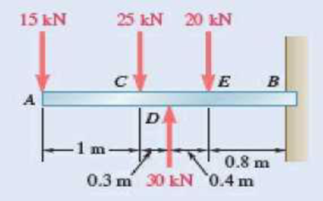
Fig. P7.35
(a)
The shear and bending-moment diagrams.
Answer to Problem 7.35P
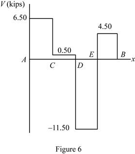
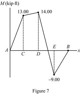
The shear diagram is drawn in figure 6 and bending momentum is drawn in figure 7.
Explanation of Solution
Refer Figure 1.
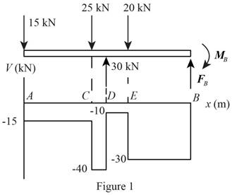
Refer Figure 2.
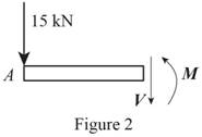
Write an expression to calculate the net counter clockwise moment at point C along AC.
Here,
Write an expression to calculate the net vertical force along AC.
Here,
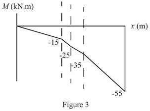
Refer Figure 3.
Write an expression to calculate the net counter clockwise moment at point D along CD.
Here,
Write an expression to calculate the net vertical force along CD.
Refer Figure 4.
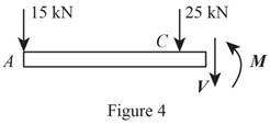
Write an expression to calculate the net counter clockwise moment at point E along DE.
Here,
Write an expression to calculate the net vertical force along EB.
Refer Figure 5.
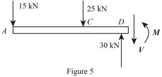
Write an expression to calculate the net counter clockwise moment at point B along EB.
Here,
Write an expression to calculate the net vertical force along EB.
Conclusion:
Refer Figure 2 and equation (II). Calculate the net vertical force.
Here,
Rearrange the equation to calculate
Refer Figure 2 and equation (I). Calculate the net counter clockwise moment at point C.
Here,
Rearrange the equation to calculate
Refer Figure 3 and equation (IV). Calculate the net vertical force.
Rearrange the equation to calculate
Refer Figure 3 and equation (III). Calculate the net counter clockwise moment at point D.
Rearrange the equation to calculate
Refer Figure 4 and equation (VI). Calculate the net vertical force.
Rearrange the equation to calculate
Refer Figure 4 and equation (V). Calculate the net counter clockwise moment at point E.
Rearrange the equation to calculate
Refer Figure 5 and equation (VIII). Calculate the net vertical force.
Rearrange the equation to calculate
Refer Figure 5 and equation (VII). Calculate the net counter clockwise moment at point E.
Rearrange the equation to calculate
Thus, draw the shear diagram.
Thus, draw the bending-moment.
(b)
The maximum absolute value of the shear and bending moment.
Answer to Problem 7.35P
The maximum absolute value of the shear force is
Explanation of Solution
Determine the maximum absolute shear from diagram 2. The maximum absolute value of bending moment is at maximum shear force.
Conclusion:
Refer figure 6. Determine the maximum absolute value of shear force.
Here,
Refer figure 7. Determine the maximum value of the bending moment at position B.
Here,
Thus, the maximum absolute value of the shear force is
Want to see more full solutions like this?
Chapter 7 Solutions
EBK VECTOR MECHANICS FOR ENGINEERS: STA


- 1. The rotating steel shaft is simply supported by bearings at points of B and C, and is driven by a spur gear at D, which has a 6-in pitch diameter. The force F from the drive gear acts at a pressure angle of 20°. The shaft transmits a torque to point A of TA =3000 lbĘ in. The shaft is machined from steel with Sy=60kpsi and Sut=80 kpsi. (1) Draw a shear force diagram and a bending moment diagram by F. According to your analysis, where is the point of interest to evaluate the safety factor among A, B, C, and D? Describe the reason. (Hint: To find F, the torque Tд is generated by the tangential force of F (i.e. Ftangential-Fcos20°) When n=2.5, K=1.8, and K₁ =1.3, determine the diameter of the shaft based on (2) static analysis using DE theory (note that fatigue stress concentration factors need to be used for this question because the loading condition is fatigue) and (3) a fatigue analysis using modified Goodman. Note) A standard diameter is not required for the questions. 10 in Darrow_forward3 N2=28 P(diametral pitch)=8 for all gears Coupled to 25 hp motor N3=34 Full depth spur gears with pressure angle=20° N₂=2000 rpm (1) Compute the circular pitch, the center-to-center distance, and base circle radii. (2) Draw the free body diagram of gear 3 and show all the forces and the torque. (3) In mounting gears, the center-to-center distance was reduced by 0.1 inch. Calculate the new values of center-to-center distance, pressure angle, base circle radii, and pitch circle diameters. (4)What is the new tangential and radial forces for gear 3? (5) Under the new center to center distance, is the contact ratio (mc) increasing or decreasing?arrow_forward2. A flat belt drive consists of two 4-ft diameter cast-iron pulleys spaced 16 ft apart. A power of 60 hp is transmitted by a pulley whose speed is 380 rev/min. Use a service factor (Ks) pf 1.1 and a design factor 1.0. The width of the polyamide A-3 belt is 6 in. Use CD=1. Answer the following questions. (1) What is the total length of the belt according to the given geometry? (2) Find the centrifugal force (Fc) applied to the belt. (3) What is the transmitted torque through the pulley system given 60hp? (4) Using the allowable tension, find the force (F₁) on the tight side. What is the tension at the loose side (F2) and the initial tension (F.)? (5) Using the forces, estimate the developed friction coefficient (f) (6) Based on the forces and the given rotational speed, rate the pulley set. In other words, what is the horse power that can be transmitted by the pulley system? (7) To reduce the applied tension on the tight side, the friction coefficient is increased to 0.75. Find out the…arrow_forward
- The tooth numbers for the gear train illustrated are N₂ = 24, N3 = 18, №4 = 30, №6 = 36, and N₁ = 54. Gear 7 is fixed. If shaft b is turned through 5 revolutions, how many turns will shaft a make? a 5 [6] barrow_forwardCE-112 please solve this problem step by step and give me the correct answerarrow_forwardCE-112 please solve this problem step by step and give me the correct answerarrow_forward
- CE-112 solve this problem step by step and give me the correct answer pleasearrow_forwardPlease do not use any AI tools to solve this question. I need a fully manual, step-by-step solution with clear explanations, as if it were done by a human tutor. No AI-generated responses, please.arrow_forwardPlease do not use any AI tools to solve this question. I need a fully manual, step-by-step solution with clear explanations, as if it were done by a human tutor. No AI-generated responses, please.arrow_forward
 International Edition---engineering Mechanics: St...Mechanical EngineeringISBN:9781305501607Author:Andrew Pytel And Jaan KiusalaasPublisher:CENGAGE L
 Principles of Heat Transfer (Activate Learning wi...Mechanical EngineeringISBN:9781305387102Author:Kreith, Frank; Manglik, Raj M.Publisher:Cengage Learning
 Mechanics of Materials (MindTap Course List)Mechanical EngineeringISBN:9781337093347Author:Barry J. Goodno, James M. GerePublisher:Cengage Learning