
MECHANICS OF MATERIALS-TEXT
9th Edition
ISBN: 2810014920922
Author: HIBBELER
Publisher: PEARSON
expand_more
expand_more
format_list_bulleted
Videos
Textbook Question
Chapter 7.2, Problem 7.27P
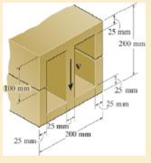
The beam is slit longitudinally along both sides. If it is subjected to a shear of V=250 kN, compare the maximum shear stress in the beam before and after the cuts were made.
Probs. 7–27/28
Expert Solution & Answer
Want to see the full answer?
Check out a sample textbook solution
Students have asked these similar questions
Please can you assist me with the attached question. Many thanks.
Please can you assist me with the attached question. Many thanks.
In using the bolt cutter shown, a worker applies two forces P to the handles. If the magnitude ofP is 500 N, determine the magnitude of the forces exerted by the cutter on the bolt
Chapter 7 Solutions
MECHANICS OF MATERIALS-TEXT
Ch. 7.2 - In each case, calculate the value of Q and t that...Ch. 7.2 - If the beam is subjected to a shear force of V =...Ch. 7.2 - Determine the shear stress at points A and B if...Ch. 7.2 - Determine the absolute maximum shear stress in the...Ch. 7.2 - If the beam is subjected to a shear force of V =20...Ch. 7.2 - If the beam is made from four plates and subjected...Ch. 7.2 - If the wide-flange beam is subjected to a shear of...Ch. 7.2 - If the wide-flange beam is subjected to a shear of...Ch. 7.2 - If the wide-flange beam is subjected to a shear of...Ch. 7.2 - Prob. 7.4P
Ch. 7.2 - Prob. 7.5PCh. 7.2 - The wood beam has an allowable shear stress of...Ch. 7.2 - The shaft is supported by a thrust bearing at A...Ch. 7.2 - The shaft is supported by a thrust bearing at A...Ch. 7.2 - Determine the largest shear force V that the...Ch. 7.2 - If the applied shear force V = 18 kip, determine...Ch. 7.2 - The overhang beam is subjected to the uniform...Ch. 7.2 - *7-12. The beam has a rectangular cross section...Ch. 7.2 - Determine the maximum shear stress in the strut if...Ch. 7.2 - Determine the maximum shear force V that the strut...Ch. 7.2 - 7-15. The strut is subjected to a vertical shear...Ch. 7.2 - Prob. 7.16PCh. 7.2 - If the beam is subjected to a shear of V=15 kN,...Ch. 7.2 - If the wide-flange beam is subjected to a shear of...Ch. 7.2 - If the wide-flange beam is subjected to a shear of...Ch. 7.2 - Prob. 7.20PCh. 7.2 - If the beam is made from wood having an allowable...Ch. 7.2 - Determine the shear stress at point B on the web...Ch. 7.2 - Determine the maximum shear stress acting at...Ch. 7.2 - Prob. 7.24PCh. 7.2 - 7-25. Determine the maximum shear stress in the...Ch. 7.2 - 7-26. The beam has a square cross section and is...Ch. 7.2 - The beam is slit longitudinally along both sides....Ch. 7.2 - The beam is to be cut longitudinally along both...Ch. 7.2 - The beam has a rectangular cross section and is...Ch. 7.2 - The beam in Fig.6-48f is subjected to a fully...Ch. 7.3 - The two identical boards are bolted together to...Ch. 7.3 - Two identical 20-mm-thick plates are bolted to the...Ch. 7.3 - The boards are bolted together to form the...Ch. 7.3 - The boards are bolted together to form the...Ch. 7.3 - Prob. 7.32PCh. 7.3 - Prob. 7.33PCh. 7.3 - Prob. 7.34PCh. 7.3 - Prob. 7.35PCh. 7.3 - Prob. 7.36PCh. 7.3 - Prob. 7.37PCh. 7.3 - Prob. 7.38PCh. 7.3 - A beam is constructed from three boards bolted...Ch. 7.3 - The simply supported beam is built up from three...Ch. 7.3 - The simply supported beam is built up from three...Ch. 7.3 - The T-beam is constructed as shown. If each nail...Ch. 7.3 - Prob. 7.43PCh. 7.3 - Prob. 7.44PCh. 7.3 - Prob. 7.45PCh. 7.3 - 7–46. The beam is subjected to a shear of V = 800...Ch. 7.3 - The beam is made from four boards nailed together...Ch. 7.3 - The beam is made from three polystyrene strips...Ch. 7.5 - A shear force of V=300 kN is applied to the box...Ch. 7.5 - A shear force of V=450 kN is applied to the box...Ch. 7.5 - A shear force of V = 18 kN is applied to the box...Ch. 7.5 - A shear force of V = 18 kN is applied to the box...Ch. 7.5 - The aluminum strut is 10 mm thick and has the...Ch. 7.5 - The aluminum strut is 10 mm thick and has the...Ch. 7.5 - Prob. 7.56PCh. 7.5 - Prob. 7.57PCh. 7.5 - Prob. 7.58PCh. 7.5 - Prob. 7.59PCh. 7.5 - The built-up beam is formed by welding together...Ch. 7.5 - The assembly is subjected to a vertical shear of V...Ch. 7.5 - 7–62. Determine the shear-stress variation over...Ch. 7.5 - 7–63. Determine the location e of the shear...Ch. 7.5 - Determine the location e of the shear center,...Ch. 7.5 - The beam supports a vertical shear of V=7 kip....Ch. 7.5 - The stiffened beam is constructed from plates...Ch. 7.5 - The pipe is subjected to a shear force of V=8 kip....Ch. 7.5 - *7–68. A thin plate of thickness t is bent to form...Ch. 7.5 - A thin plate of thickness t is bent to form the...Ch. 7.5 - 7–70. Determine the location e of the shear...Ch. 7 - The beam is fabricated from four boards nailed...Ch. 7 - The T-beam is subjected to a shear of V = 150 kN....Ch. 7 - The member is subject to a shear force of V = 2...Ch. 7 - Determine the shear stress at points B and C on...Ch. 7 - Determine the maximum shear stress acting at...
Knowledge Booster


Learn more about
Need a deep-dive on the concept behind this application? Look no further. Learn more about this topic, mechanical-engineering and related others by exploring similar questions and additional content below.Similar questions
- Arterioles bifurcate (i.e., split) into capillaries in the circulatory system. Blood flows at a velocity of 20 cm/s through an arteriole with a diameter of 0.20 cm. This vessel bifurcates into two vessels: one with a diameter of 0.17 cm and a blood flow velocity of 18 cm/sec, and one with a diameter of 0.15 cm. Each of these two vessels splits again. The 0.17-cm diameter vessel splits into two vessels, each with a diameter of 0.15 cm. The 0.15-cm diameter vessel splits into two vessels, each with a diameter of 0.12 cm. Determine the mass flow rate and velocity of blood in each of the four vessels at the end of the arteriole bifurcations. You may need to set up several systems, each with a different system boundary, in order to solve this problem.arrow_forward6) Draw a Front, side and Top view for the following objects: p.s. you don't need to label the alphabet ISOMETRIC PICTORIAL VIEW K R C B E R D 0 Aarrow_forwardPlease draw the front top and side view for the following objectarrow_forward
- Draw the top viewarrow_forwardSuppose that a steel of eutectoid composition is cooled to 675°C (1250°F) from 760°C (1400°F) in less than 0.5 s and held at this temperature. (a) How long will it take for the austenite-topearlite reaction to go to 50% completion? To 100% completion? (b) Estimate the hardness of the alloy that has completely transformed to pearlite.arrow_forwardProblem 2: Determine the components of the reaction at point B (Please use paper sheet + FBD ,don't use chatgpt) MECHANICAL ENGGarrow_forward
- ARL040_AE_Kn_2of3... Dor Question 4. A two-throw crankshaft has masses distributed as shown: RAH 90 rpm A TRAV B Re Rev M₁ = 15kg; M₂ = 12kg L = 950mm; 1, 350mm; 1₁ = 600mm; 0₁ = 90°; 02=0°; r₁ = 300mm; r250mm The crankshaft is to be balanced by attaching masses at radii of 300 mm and rotating in planes 150 mm outside the planes of number one and number two cranks. Determine the magnitude and angular position of the balance masses. Answer 4.arrow_forwardFEAarrow_forwardFinite Element Analysisarrow_forward
- an experimental research station is constructed on a concrete slab floor. The heat loss from the floor slab is significant, given the cold environment, and is measured to be 5 kW. The edges of the floor slab are insulated with a 60 mm thickness of cellular glass insulation. The width of this insulation at the floor slab is 0.9 m. To avoid excessive fuel consumption, the station air temperature is maintained at a slightly cool temperature of 18ºC. The station is constructed in a square shape, to keep the surface area to volume ratio low; the horizontal dimensions of the floor of the station are 20 m by 20 m. The number of occupants in the research station varies between 5 and 20, depending on the research workload.a) Determine the design outdoor temperature that was used in designing the research station.b) If the floor dimensions of the station are changed to 15 m by 25 m, would the design outdoor temperature that was used in designing the research station from part (a) change? If so,…arrow_forwardFinite element analysisarrow_forwarda station is constructed on a concrete slab floor. The heat loss from the floor slab is significant, given the cold environment, and is measured to be 5 kW. The edges of the floor slab are insulated with a 60 mm thickness of cellular glass insulation. The width of this insulation at the floor slab is 0.9 m. To avoid excessive fuel consumption, the station air temperature is maintained at a slightly cool temperature of 18ºC. The station is constructed in a square shape, to keep the surface area to volume ratio low; the horizontal dimensions of the floor of the station are 20 m by 20 m. The number of occupants in the research station varies between 5 and 20, depending on the research workload.a) Determine the design outdoor temperature that was used in designing the research station.b) If the floor dimensions of the station are changed to 15 m by 25 m, would the design outdoor temperature that was used in designing the research station from part (a) change? If so, what would it be?…arrow_forward
arrow_back_ios
SEE MORE QUESTIONS
arrow_forward_ios
Recommended textbooks for you
 Elements Of ElectromagneticsMechanical EngineeringISBN:9780190698614Author:Sadiku, Matthew N. O.Publisher:Oxford University Press
 Mechanics of Materials (10th Edition)Mechanical EngineeringISBN:9780134319650Author:Russell C. HibbelerPublisher:PEARSON
 Thermodynamics: An Engineering ApproachMechanical EngineeringISBN:9781259822674Author:Yunus A. Cengel Dr., Michael A. BolesPublisher:McGraw-Hill Education
 Control Systems EngineeringMechanical EngineeringISBN:9781118170519Author:Norman S. NisePublisher:WILEY
 Mechanics of Materials (MindTap Course List)Mechanical EngineeringISBN:9781337093347Author:Barry J. Goodno, James M. GerePublisher:Cengage Learning
 Engineering Mechanics: StaticsMechanical EngineeringISBN:9781118807330Author:James L. Meriam, L. G. Kraige, J. N. BoltonPublisher:WILEY
Elements Of Electromagnetics
Mechanical Engineering
ISBN:9780190698614
Author:Sadiku, Matthew N. O.
Publisher:Oxford University Press
Mechanics of Materials (10th Edition)
Mechanical Engineering
ISBN:9780134319650
Author:Russell C. Hibbeler
Publisher:PEARSON
Thermodynamics: An Engineering Approach
Mechanical Engineering
ISBN:9781259822674
Author:Yunus A. Cengel Dr., Michael A. Boles
Publisher:McGraw-Hill Education
Control Systems Engineering
Mechanical Engineering
ISBN:9781118170519
Author:Norman S. Nise
Publisher:WILEY
Mechanics of Materials (MindTap Course List)
Mechanical Engineering
ISBN:9781337093347
Author:Barry J. Goodno, James M. Gere
Publisher:Cengage Learning
Engineering Mechanics: Statics
Mechanical Engineering
ISBN:9781118807330
Author:James L. Meriam, L. G. Kraige, J. N. Bolton
Publisher:WILEY
Differences between Temporary Joining and Permanent Joining.; Author: Academic Gain Tutorials;https://www.youtube.com/watch?v=PTr8QZhgXyg;License: Standard Youtube License