
MECHANICS OF MATERIALS-TEXT
9th Edition
ISBN: 2810014920922
Author: HIBBELER
Publisher: PEARSON
expand_more
expand_more
format_list_bulleted
Videos
Textbook Question
Chapter 7.5, Problem 7.67P
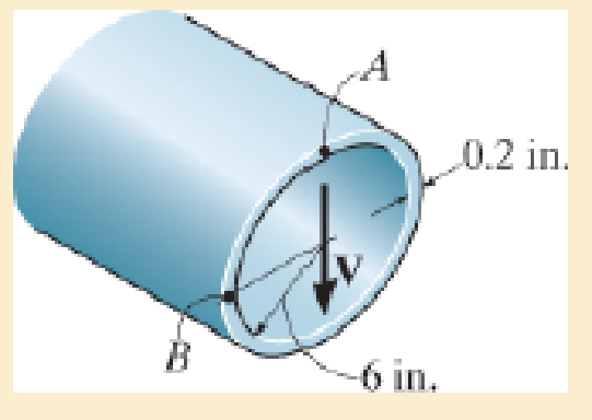
The pipe is subjected to a shear force of V=8 kip. Determine the shear flow in the pipe at points A and B.
Expert Solution & Answer
Want to see the full answer?
Check out a sample textbook solution
Students have asked these similar questions
Please answer
Oxygen at 300 kPa and 90°C flowing at an average velocity of 3 m/s is expanded in an adiabatic nozzle. What is the maximum velocity of the oxygen at the outlet of this nozzle when the outlet pressure is 60 kPa? Use the table containing the ideal gas specific heats of various common gases.
The maximum velocity of the oxygen at the outlet of this nozzle is 532.5 Numeric ResponseEdit Unavailable. 532.5 incorrect.m/s.
A container filled with 70 kg of liquid water at 95°C is placed in a 90-m3 room that is initially at 12°C. Thermal equilibrium is established after a while as a result of heat transfer between the water and the air in the room. Assume the room is at the sea level, well sealed, and heavily insulated.
NOTE: This is a multi-part question. Once an answer is submitted, you will be unable to return to this part.
Determine the amount of heat transfer between the water and the air in the room.
The amount of heat transfer between the water and the air in the room is kJ.
A strain gauge rosette that is attached to the surface of a stressed component
gives 3 readings (ɛa = A, b = B, &c = C). If the strain gauge rosette is of the D°
type (indicating the angle between each of the gauges), construct a Mohr's Strain
Circle overleaf. You should assume that gauge A is aligned along the x-axis.
Using the Mohr's Strain Circle calculate the:
(i) principal strains (ε1, 2)?
(ii) principal angles (1, 2)?
You should measure these anticlockwise from the y-axis.
(iii) maximum shear strain in the plane (ymax)?
Chapter 7 Solutions
MECHANICS OF MATERIALS-TEXT
Ch. 7.2 - In each case, calculate the value of Q and t that...Ch. 7.2 - If the beam is subjected to a shear force of V =...Ch. 7.2 - Determine the shear stress at points A and B if...Ch. 7.2 - Determine the absolute maximum shear stress in the...Ch. 7.2 - If the beam is subjected to a shear force of V =20...Ch. 7.2 - If the beam is made from four plates and subjected...Ch. 7.2 - If the wide-flange beam is subjected to a shear of...Ch. 7.2 - If the wide-flange beam is subjected to a shear of...Ch. 7.2 - If the wide-flange beam is subjected to a shear of...Ch. 7.2 - Prob. 7.4P
Ch. 7.2 - Prob. 7.5PCh. 7.2 - The wood beam has an allowable shear stress of...Ch. 7.2 - The shaft is supported by a thrust bearing at A...Ch. 7.2 - The shaft is supported by a thrust bearing at A...Ch. 7.2 - Determine the largest shear force V that the...Ch. 7.2 - If the applied shear force V = 18 kip, determine...Ch. 7.2 - The overhang beam is subjected to the uniform...Ch. 7.2 - *7-12. The beam has a rectangular cross section...Ch. 7.2 - Determine the maximum shear stress in the strut if...Ch. 7.2 - Determine the maximum shear force V that the strut...Ch. 7.2 - 7-15. The strut is subjected to a vertical shear...Ch. 7.2 - Prob. 7.16PCh. 7.2 - If the beam is subjected to a shear of V=15 kN,...Ch. 7.2 - If the wide-flange beam is subjected to a shear of...Ch. 7.2 - If the wide-flange beam is subjected to a shear of...Ch. 7.2 - Prob. 7.20PCh. 7.2 - If the beam is made from wood having an allowable...Ch. 7.2 - Determine the shear stress at point B on the web...Ch. 7.2 - Determine the maximum shear stress acting at...Ch. 7.2 - Prob. 7.24PCh. 7.2 - 7-25. Determine the maximum shear stress in the...Ch. 7.2 - 7-26. The beam has a square cross section and is...Ch. 7.2 - The beam is slit longitudinally along both sides....Ch. 7.2 - The beam is to be cut longitudinally along both...Ch. 7.2 - The beam has a rectangular cross section and is...Ch. 7.2 - The beam in Fig.6-48f is subjected to a fully...Ch. 7.3 - The two identical boards are bolted together to...Ch. 7.3 - Two identical 20-mm-thick plates are bolted to the...Ch. 7.3 - The boards are bolted together to form the...Ch. 7.3 - The boards are bolted together to form the...Ch. 7.3 - Prob. 7.32PCh. 7.3 - Prob. 7.33PCh. 7.3 - Prob. 7.34PCh. 7.3 - Prob. 7.35PCh. 7.3 - Prob. 7.36PCh. 7.3 - Prob. 7.37PCh. 7.3 - Prob. 7.38PCh. 7.3 - A beam is constructed from three boards bolted...Ch. 7.3 - The simply supported beam is built up from three...Ch. 7.3 - The simply supported beam is built up from three...Ch. 7.3 - The T-beam is constructed as shown. If each nail...Ch. 7.3 - Prob. 7.43PCh. 7.3 - Prob. 7.44PCh. 7.3 - Prob. 7.45PCh. 7.3 - 7–46. The beam is subjected to a shear of V = 800...Ch. 7.3 - The beam is made from four boards nailed together...Ch. 7.3 - The beam is made from three polystyrene strips...Ch. 7.5 - A shear force of V=300 kN is applied to the box...Ch. 7.5 - A shear force of V=450 kN is applied to the box...Ch. 7.5 - A shear force of V = 18 kN is applied to the box...Ch. 7.5 - A shear force of V = 18 kN is applied to the box...Ch. 7.5 - The aluminum strut is 10 mm thick and has the...Ch. 7.5 - The aluminum strut is 10 mm thick and has the...Ch. 7.5 - Prob. 7.56PCh. 7.5 - Prob. 7.57PCh. 7.5 - Prob. 7.58PCh. 7.5 - Prob. 7.59PCh. 7.5 - The built-up beam is formed by welding together...Ch. 7.5 - The assembly is subjected to a vertical shear of V...Ch. 7.5 - 7–62. Determine the shear-stress variation over...Ch. 7.5 - 7–63. Determine the location e of the shear...Ch. 7.5 - Determine the location e of the shear center,...Ch. 7.5 - The beam supports a vertical shear of V=7 kip....Ch. 7.5 - The stiffened beam is constructed from plates...Ch. 7.5 - The pipe is subjected to a shear force of V=8 kip....Ch. 7.5 - *7–68. A thin plate of thickness t is bent to form...Ch. 7.5 - A thin plate of thickness t is bent to form the...Ch. 7.5 - 7–70. Determine the location e of the shear...Ch. 7 - The beam is fabricated from four boards nailed...Ch. 7 - The T-beam is subjected to a shear of V = 150 kN....Ch. 7 - The member is subject to a shear force of V = 2...Ch. 7 - Determine the shear stress at points B and C on...Ch. 7 - Determine the maximum shear stress acting at...
Knowledge Booster


Learn more about
Need a deep-dive on the concept behind this application? Look no further. Learn more about this topic, mechanical-engineering and related others by exploring similar questions and additional content below.Similar questions
- Q1. If the yield stress (σy) of a material is 375MPa, determine whether yield is predicted for the stresses acting on both the elements shown below using: (a) Tresca Criterion (b) Von Mises Criterion P Element A R S Element B Note: your values for P (vertical load on Element A) should be negative (i.e. corresponding to a compressive vertical load).arrow_forwardQ. After a puncture a driver is attempting to remove a wheel nut by applying a force of P KN to one end of a wheel brace as shown in Fig. 1. In cross-section the brace is a hollow steel tube (see section aa) of internal diameter r mm and external diameter q mm. wheel nut n Position S P m r q Section aa Fig, 1 (a) Calculate (i) the twisting moment, (ii) the bending moment, and (iii) the shear force in the brace at position S due to the applied load P. (b) Calculate (i) the shear stress due to twisting, and (ii) the bending stress at position S. Note that the shear force will not produce any shear stress at S. (c) Calculate the maximum shearing stress in the brace at position S using the Maximum Shear Stress Criterion. 2 Mechanics of Materials 2 Tutorials Portfolio: Exercise 5 (d) If the maximum permissible shear stress in the steel is 200 MPa, determine the maximum torque that can be applied by the brace without the risk of failure at S.arrow_forwardCalculate the first 5 Fourier series coefficients (A0-4 and B1-5 ) for the estimated R wave.arrow_forward
- Refrigerant-134a is expanded isentropically from 600 kPa and 70°C at the inlet of a steady-flow turbine to 100 kPa at the outlet. The outlet area is 1 m2, and the inlet area is 0.5 m2. Calculate the inlet and outlet velocities when the mass flow rate is 0.65 kg/s. Use the tables for R-134a. The inlet velocity is m/s. The outlet velocity is m/s.arrow_forwardA container filled with 70 kg of liquid water at 95°C is placed in a 90-m3 room that is initially at 12°C. Thermal equilibrium is established after a while as a result of heat transfer between the water and the air in the room. Assume the room is at the sea level, well sealed, and heavily insulated. NOTE: This is a multi-part question. Once an answer is submitted, you will be unable to return to this part. Determine the final equilibrium temperature. Use the table containing the ideal gas specific heats of various common gases. The final equilibrium temperature is °C.arrow_forwardSteam at 100 psia and 650°F is expanded adiabatically in a closed system to 10 psia. Determine the work produced, in Btu/lbm, and the final temperature of steam for an isentropic expansion efficiency of 80 percent. Use steam tables. The work produced is Btu/lbm. The final temperature of steam is °F.arrow_forward
- Complet the solution : Vavg Ti Te Ts Q hexp Nuexp htheo Re Nutheo Error (m/s) (*C) (*C) (*C) (W) 2.11 18.8 21.3 45.8 2.61 18.5 20.8 46.3arrow_forwardA 48-kg iron block and a 76-kg copper block, both initially at 80°C, are dropped into a large lake at 15°C. Thermal equilibrium is established after a while as a result of heat transfer between the blocks and the lake water. Determine the total entropy change for this process. The specific heat of iron at room temperature is cp = 0.45 kJ/kg·K. The specific heat of copper at 27°C is cp = 0.386 kJ/kg·K. The total entropy change for this process is kJ/K.arrow_forwardPlease help Air at 4.4 MPa and 500°C is expanded in an adiabatic gas turbine to 0.2 MPa. Calculate the maximum work that this turbine can produce in kJ/kg. Use the table containing the ideal gas specific heats of various common gases. The maximum work that this turbine can produce is kJ/kg.arrow_forward
- Saturated water vapor at 150°C is compressed in a reversible steady-flow device to 1150 kPa while its specific volume remains constant. Determine the work required in kJ/kg. Use steam tables. The work required is kJ/kg.arrow_forwardThree lbm of R-134a is expanded isentropically in a closed system from 100 psia and 100°F to 10 psia. Determine the total heat transfer and the work production for this process. Use the tables for R-134a. The total heat transfer is Btu. The work production for this process is Btu. Three lbm of R-134a is expanded isentropically in a closed system from 100 psia and 100°F to 10 psia. Determine the total heat transfer and the work production for this process. Use the tables for R-134a. The total heat transfer is Btu. The work production for this process is Btu.arrow_forwardOxygen at 300 kPa and 90°C flowing at an average velocity of 3 m/s is expanded in an adiabatic nozzle. What is the maximum velocity of the oxygen at the outlet of this nozzle when the outlet pressure is 60 kPa? Use the table containing the ideal gas specific heats of various common gases. The maximum velocity of the oxygen at the outlet of this nozzle is m/s.arrow_forward
arrow_back_ios
SEE MORE QUESTIONS
arrow_forward_ios
Recommended textbooks for you
 Elements Of ElectromagneticsMechanical EngineeringISBN:9780190698614Author:Sadiku, Matthew N. O.Publisher:Oxford University Press
 Mechanics of Materials (10th Edition)Mechanical EngineeringISBN:9780134319650Author:Russell C. HibbelerPublisher:PEARSON
 Thermodynamics: An Engineering ApproachMechanical EngineeringISBN:9781259822674Author:Yunus A. Cengel Dr., Michael A. BolesPublisher:McGraw-Hill Education
 Control Systems EngineeringMechanical EngineeringISBN:9781118170519Author:Norman S. NisePublisher:WILEY
 Mechanics of Materials (MindTap Course List)Mechanical EngineeringISBN:9781337093347Author:Barry J. Goodno, James M. GerePublisher:Cengage Learning
 Engineering Mechanics: StaticsMechanical EngineeringISBN:9781118807330Author:James L. Meriam, L. G. Kraige, J. N. BoltonPublisher:WILEY
Elements Of Electromagnetics
Mechanical Engineering
ISBN:9780190698614
Author:Sadiku, Matthew N. O.
Publisher:Oxford University Press
Mechanics of Materials (10th Edition)
Mechanical Engineering
ISBN:9780134319650
Author:Russell C. Hibbeler
Publisher:PEARSON
Thermodynamics: An Engineering Approach
Mechanical Engineering
ISBN:9781259822674
Author:Yunus A. Cengel Dr., Michael A. Boles
Publisher:McGraw-Hill Education
Control Systems Engineering
Mechanical Engineering
ISBN:9781118170519
Author:Norman S. Nise
Publisher:WILEY
Mechanics of Materials (MindTap Course List)
Mechanical Engineering
ISBN:9781337093347
Author:Barry J. Goodno, James M. Gere
Publisher:Cengage Learning
Engineering Mechanics: Statics
Mechanical Engineering
ISBN:9781118807330
Author:James L. Meriam, L. G. Kraige, J. N. Bolton
Publisher:WILEY
Everything About TRANSVERSE SHEAR in 10 Minutes!! - Mechanics of Materials; Author: Less Boring Lectures;https://www.youtube.com/watch?v=4x0E9yvzfCM;License: Standard Youtube License