
INTERNATIONAL EDITION---Engineering Mechanics: Statics, 14th edition (SI unit)
14th Edition
ISBN: 9780133918922
Author: Russell C. Hibbeler
Publisher: PEARSON
expand_more
expand_more
format_list_bulleted
Concept explainers
Videos
Textbook Question
Chapter 7.2, Problem 58P
Draw the shear and bending-moment diagrams for each of the two segments of the compound beam.
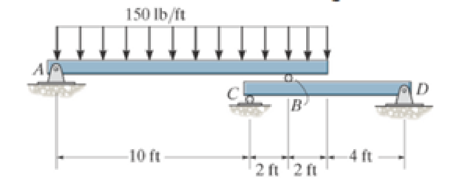
Prob. 7–58
Expert Solution & Answer
Want to see the full answer?
Check out a sample textbook solution
Students have asked these similar questions
subject: combustion
please include complete solution, no rounding off, with diagram/explanation etc.
A gasoline engine, utilizing cold air, recorded a work of 431 BTU/lb at a maximum temperature of 3,273 K and 1112 deg F temperature at the beginning of constant volume heat addition. What is the compression ratio?
subject: combustion
please do step by step solution and no rounding off, complete solution with diagram/explanation if needed etc. thank you!
Air enters the compressor at 101,320 Pascals, 305.15K, and leaves at a pressure of 0.808MPa. The air is heated to 990.15K in the combustion chamber. For a net output of 2,125,000 Watts, find the rate of flow of air per second.
The link lengths and the value of 2 and offset for some fourbar crank-slide linkages are defined
in Table 1. The linkage configuration and terminology are shown in Figure 1. For the rows
assigned, find
(a) all possible solutions for angle & and slider position d by vector loop method.
(b) the transmission angle corresponding to angle 03. (Hint: Treat the vector R4 as virtual rocker)
Show your work in details: vector loop, vector equations, solution procedure.
Table 1
Row
Link 2
Link 3
Offset
Ө
a
1.4
4
1
45°
b
3
8
2
-30°
C
5
20
-5
225°
03
slider axis
B
X
offset
Link 2
A
R3
Link 3
R4
04
R2
02
R1
d
Figure 1.
X
Chapter 7 Solutions
INTERNATIONAL EDITION---Engineering Mechanics: Statics, 14th edition (SI unit)
Ch. 7.1 - In each case, calculate the reaction at A and then...Ch. 7.1 - Determine the normal force, shear force, and...Ch. 7.1 - Determine the normal force, shear force, and...Ch. 7.1 - Determine the normal force, shear force, and...Ch. 7.1 - Determine the normal force, shear force, and...Ch. 7.1 - Determine the normal force, shear force, and...Ch. 7.1 - Assume A is pinned and B is a roller. Prob. F7-6Ch. 7.1 - Determine the shear force and moment at points C...Ch. 7.1 - Assume the support at B is a roller. Point C is...Ch. 7.1 - Determine the internal normal force, shear force,...
Ch. 7.1 - Determine the internal normal force, shear force,...Ch. 7.1 - If a force of 20 lb is applied to the handles,...Ch. 7.1 - Determine the distance a as a fraction of the...Ch. 7.1 - Determine the internal shear force and moment...Ch. 7.1 - Determine the internal shear force and moment...Ch. 7.1 - Take P = 8 kN. Prob. 7-9Ch. 7.1 - Determine the largest vertical load P the frame...Ch. 7.1 - Determine the internal normal force, shear force,...Ch. 7.1 - Determine the distance a between the bearings in...Ch. 7.1 - Point D is located just to the left of the 5-kip...Ch. 7.1 - The shaft is supported by a journal bearing at A...Ch. 7.1 - Determine the internal normal force, shear force,...Ch. 7.1 - Determine the internal normal force, shear force,...Ch. 7.1 - Determine the normal force, shear force, and...Ch. 7.1 - Determine the internal normal force, shear force,...Ch. 7.1 - Prob. 19PCh. 7.1 - Determine the internal normal force, shear force,...Ch. 7.1 - Point E is located just to the left of 800 N...Ch. 7.1 - Point D is located just to the left of the roller...Ch. 7.1 - Determine the internal normal force, shear force,...Ch. 7.1 - Determine the ratio of a/b for which the shear...Ch. 7.1 - Point E is just to the right of the 3-kip load....Ch. 7.1 - Determine the internal normal force, shear force,...Ch. 7.1 - Determine the internal normal force, shear force,...Ch. 7.1 - Point D is located just to the left of the 10-kN...Ch. 7.1 - Determine the normal force, shear force, and...Ch. 7.1 - Determine the normal force, shear force, and...Ch. 7.1 - Determine the internal normal force, shear force,...Ch. 7.1 - Determine the internal normal force, shear force,...Ch. 7.1 - Determine the internal normal force, shear force,...Ch. 7.1 - Determine the internal normal force, shear force,...Ch. 7.1 - If the suspended load has a weight of 2 kN and a...Ch. 7.1 - Determine the internal normal force, shear force,...Ch. 7.1 - Determine the internal normal force, shear force,...Ch. 7.1 - Determine the internal normal force, shear force,...Ch. 7.1 - The distributed loading W = W0 sin , measured per...Ch. 7.1 - Solve Prob. 7-39 for = 120. Probs. 739/40Ch. 7.1 - z components of force and moment at point C in the...Ch. 7.1 - Determine the x, y, z components of force and...Ch. 7.1 - Determine the x, y, z components of internal...Ch. 7.1 - Determine the x, y. z components of internal...Ch. 7.2 - Determine the shear and moment as a function of x,...Ch. 7.2 - Determine the shear and moment as a function of x,...Ch. 7.2 - Determine the shear and moment as a function of x,...Ch. 7.2 - Determine the shear and moment as a function of x,...Ch. 7.2 - Determine the shear and moment as a function of x,...Ch. 7.2 - Determine the shear and moment as a function of x,...Ch. 7.2 - Draw the shear and moment diagrams for the shaft...Ch. 7.2 - Draw the shear and moment diagrams for the beam...Ch. 7.2 - Draw the shear and moment diagrams for the beam...Ch. 7.2 - Draw the shear and moment diagrams for the...Ch. 7.2 - Draw the shear and moment diagrams of the beam (a)...Ch. 7.2 - If L = 9 m, the beam will fail when the maximum...Ch. 7.2 - Draw the shear and moment diagrams for the beam....Ch. 7.2 - Draw the shear and moment diagrams for the beam....Ch. 7.2 - Draw the shear and bending-moment diagrams for the...Ch. 7.2 - The shaft is supported by a smooth thrust bearing...Ch. 7.2 - Draw the shear and moment diagrams for the beam....Ch. 7.2 - Draw the shear and moment diagrams for the beam....Ch. 7.2 - Draw the shear and moment diagrams for the...Ch. 7.2 - Draw the shear and bending-moment diagrams for...Ch. 7.2 - Draw the shear and moment diagrams for the beam....Ch. 7.2 - The shaft is supported by a smooth thrust bearing...Ch. 7.2 - Draw the shear and moment diagrams for the beam....Ch. 7.2 - The beam will fail when the maximum internal...Ch. 7.2 - Draw the shear and moment diagrams for the beam....Ch. 7.2 - Draw the shear and moment diagrams for the beam....Ch. 7.2 - Draw the shear and moment diagrams for the beam....Ch. 7.2 - Draw the shear and moment diagrams for the beam....Ch. 7.2 - Determine the internal normal force, shear force,...Ch. 7.2 - The quarter circular rod lies in the horizontal...Ch. 7.2 - Express the internal shear and moment components...Ch. 7.3 - Draw the shear and moment diagrams for the beam....Ch. 7.3 - Draw the shear and moment diagrams for the beam....Ch. 7.3 - Draw the shear and moment diagrams for the beam....Ch. 7.3 - Draw the shear and moment diagrams for the beam....Ch. 7.3 - Draw the shear and moment diagrams for the beam....Ch. 7.3 - Draw the shear and moment diagrams for the beam....Ch. 7.3 - Draw the shear and moment diagrams for the beam....Ch. 7.3 - Draw the shear and moment diagrams for the beam....Ch. 7.3 - Draw the shear and moment diagrams for the beam....Ch. 7.3 - Draw the shear and moment diagrams for the...Ch. 7.3 - Draw the shear and moment diagrams for the beam....Ch. 7.3 - Draw the shear and moment diagrams for the beam....Ch. 7.3 - Draw the shear and moment diagrams for the beam....Ch. 7.3 - Draw the shear and moment diagrams for the beam....Ch. 7.3 - Draw the shear and moment diagrams for the beam....Ch. 7.3 - Draw the shear and moment diagrams for the shaft....Ch. 7.3 - Draw the shear and moment diagrams for the beam....Ch. 7.3 - The beam consists of three segments pin connected...Ch. 7.3 - Draw the shear and moment diagrams for the beam....Ch. 7.3 - Draw the shear and moment diagrams for the beam....Ch. 7.3 - Draw the shear and moment diagrams for the beam....Ch. 7.3 - Draw the shear and moment diagrams for the beam....Ch. 7.3 - Draw the shear and moment diagrams for the beam....Ch. 7.3 - Draw the shear and moment diagrams for the beam....Ch. 7.3 - Draw the shear and moment diagrams for the beam....Ch. 7.3 - Draw the shear and moment diagrams for the beam....Ch. 7.3 - Draw the shear and moment diagrams for the beam....Ch. 7.3 - Draw the shear and moment diagrams for the beam....Ch. 7.3 - Draw the shear and moment diagrams for the beam....Ch. 7.3 - Draw the shear and moment diagrams for the beam....Ch. 7.4 - The cable supports the three loads shown....Ch. 7.4 - The cable supports the three loads shown....Ch. 7.4 - Determine the tension in each segment of the cable...Ch. 7.4 - The cable supports the loading shown. Determine...Ch. 7.4 - The cable supports the loading shown. Determine...Ch. 7.4 - The cable supports the three loads shown....Ch. 7.4 - The cable supports the three loads shown....Ch. 7.4 - Determine the force P needed to hold the cable in...Ch. 7.4 - Determine the maximum uniform loading w, measured...Ch. 7.4 - The cable is subjected to a uniform loading of w =...Ch. 7.4 - The cable AB is subjected to a uniform loading of...Ch. 7.4 - Prob. 105PCh. 7.4 - If yB = 1.5 ft. determine the largest weight of...Ch. 7.4 - The cable supports a girder which weighs 850...Ch. 7.4 - Prob. 108PCh. 7.4 - If the pipe has a mass per unit length of 1500...Ch. 7.4 - Prob. 110PCh. 7.4 - Determine the maximum tension developed in the...Ch. 7.4 - Prob. 112PCh. 7.4 - The cable is subjected to the parabolic loading w...Ch. 7.4 - The power transmission cable weighs 10 lb/fl. If...Ch. 7.4 - The power transmission cable weighs 10 lb/ft. If h...Ch. 7.4 - The man picks up the 52-ft chain and holds it just...Ch. 7.4 - Prob. 117PCh. 7.4 - Prob. 118PCh. 7.4 - Prob. 119PCh. 7.4 - A telephone line (cable) stretches between two...Ch. 7.4 - Prob. 121PCh. 7.4 - Prob. 122PCh. 7.4 - A cable has a weight of 5 lb/ft. If it can span...Ch. 7.4 - Prob. 124PCh. 7.4 - Determine the internal normal force, shear force,...Ch. 7.4 - Determine the normal force, shear force, and...Ch. 7.4 - Draw the shear and moment diagrams for the beam....Ch. 7.4 - Draw the shear and moment diagrams for the beam....Ch. 7.4 - Draw the shear and moment diagrams for the beam....Ch. 7.4 - Prob. 6RP
Knowledge Booster


Learn more about
Need a deep-dive on the concept behind this application? Look no further. Learn more about this topic, mechanical-engineering and related others by exploring similar questions and additional content below.Similar questions
- 4. Two links made of heat treated 6061 aluminum (Sy = 276 MPa, Sys = 160 MPa) are pinned together using a steel dowel pin (Sy = 1398 MPa, Sys = 806 MPa) as shown below. The links are to support a load P with a factor of safety of at least 2.0. Determine if the link will fail first by tearout, direct shear of the pin, bearing stress on the link, or tensile stress at section AA. (Hint: find the load P for each case and choose the case that gives the smallest load.) P 8 mm P 8 mm ¡+A 3 mm →A 10 mm Parrow_forward1. For a feature other than a sphere, circularity is where: A. The axis is a straight line B. The modifier is specified with a size dimension C. All points of the surface intersected by any plane perpendicular to an axis or spine (curved line) are equidistant from that axis or spine D. All points of the surface intersected by any plane passing through a common center are equidistant from that center 2. What type of variation is limited by a circularity toler- ance zone? A. Ovality B. Tapering C. Bending D. Warping 3. How does the Rule #1 boundary affect the application of a circularity tolerance? A. The modifier must be used. B. The feature control frame must be placed next to the size dimension. C. The circularity tolerance value must be less than the limits of size tolerance. D. Circularity cannot be applied where a Rule #1 boundary exists. 4. A circularity tolerance may use a modifier. A. Ø B. F C. M D. ℗ 5. A real-world application for a circularity tolerance is: A. Assembly (i.e.,…arrow_forward3. A steel bar is pinned to a vertical support column by a 10 mm diameter hardened dowel pin, Figure 1. For P = 7500 N, find: a. the shear stress in the pin, b. the direct bearing stress on the hole in the bar, c. the minimum value of d to prevent tearout failure if the steel bar has a shear strength of 175 MPa. support column pin bar thickness of bar = 8 mm h d 150 mmarrow_forward
- A press that delivers 115 strokes per minute, each stroke providing a force of 7826 N throughout a distance of 18 mm. The press efficiency is 90% and is driven by a 1749-rpm motor. Determine average torque that must be provided by the motor in the units of N-m.arrow_forward·3) find the force (P) for the figures (1) and (2) 15cm 10cm 15 h=10mm h2=6mm // Call = 90 N/2 P Agate Fig (i) Ans: 1)P=112614N 2) P=1956.5 N 25cm 25 cm الفترة أو الحجم تمر بالتي عثر اكو تورشن (ک Fig (2) h₁ = 10mm 42=6mm Cmarrow_forwardI want a human solutionarrow_forward
- (Read Image)arrow_forward47 14 16 12 34 10 12 12 33arrow_forward3. A steam power plant has an average monthly net power delivery of 740 MW over the course of a year. This power delivery is accomplished by burning coal in the boiler. The coal has a heating value of 9150 Btu/lbm. The cost of the coal is $14.20/ton. The overall thermal efficiency of the plant is, nth = Wnet Qboiler = 0.26 = 26% Determine the annual cost of the coal required to deliver the given average monthly power.arrow_forward
- 47 14 16 12 34 10 12 12 33arrow_forward= The forces F₁ = 590 lb, F₂ = 380 lb, F3 = 240 lb and F 330 lb. Determine the forces in each member of the truss. Use positive values to indicate tension and negative values to indicate compression. a a a D b F₁ A 000 B. 779977 F₂V H G E F4 b BY NC SA 2013 Michael Swanbom Values for dimensions on the figure are given in the following table. Note the figure may not be to scale. Variable Value a 6 ft b 10.1 ft The force in member AB is lb. The force in member AH is lb. The force in member GH is lb. The force in member BH is lb. The force in member BC is lb. The force in member BG is lb. The force in member EG is lb. The force in member CD is lb. The force in member DE is lb. The force in member CE is lb. The force in member CG is lb.arrow_forwardMultiple Choice Circle the best answer to each statement. 1. Which type of surface deviation is controlled by a cy- lindricity tolerance but not by a circularity tolerance? A. B. C. Ovality Taper Lobing D. None of the above 2. When verifying a cylindricity tolerance, the inspec- tion method must be able to collect a set of points and determine the: A. Distance between two coaxial cylinders that con- tain the set of points B. Cylinder that circumscribes the set of points C. Cylinder that inscribes the set of points D. Distance between two coaxial circles that contain the set of points 3. Where Rule #1 applies to a cylindrical regular feature of size, the tolerance value of a cylindricity tolerance applied to the feature of size must be tolerance. A. Less than B. Equal to C. Greater than D. None of the above the size 4. Which of the following modifiers may be applied with a cylindricity tolerance? A. M B. C. ℗ D. Ø 5. Which geometric tolerance can provide an indirect cylindricity…arrow_forward
arrow_back_ios
SEE MORE QUESTIONS
arrow_forward_ios
Recommended textbooks for you
 Elements Of ElectromagneticsMechanical EngineeringISBN:9780190698614Author:Sadiku, Matthew N. O.Publisher:Oxford University Press
 Mechanics of Materials (10th Edition)Mechanical EngineeringISBN:9780134319650Author:Russell C. HibbelerPublisher:PEARSON
 Thermodynamics: An Engineering ApproachMechanical EngineeringISBN:9781259822674Author:Yunus A. Cengel Dr., Michael A. BolesPublisher:McGraw-Hill Education
 Control Systems EngineeringMechanical EngineeringISBN:9781118170519Author:Norman S. NisePublisher:WILEY
 Mechanics of Materials (MindTap Course List)Mechanical EngineeringISBN:9781337093347Author:Barry J. Goodno, James M. GerePublisher:Cengage Learning
 Engineering Mechanics: StaticsMechanical EngineeringISBN:9781118807330Author:James L. Meriam, L. G. Kraige, J. N. BoltonPublisher:WILEY
Elements Of Electromagnetics
Mechanical Engineering
ISBN:9780190698614
Author:Sadiku, Matthew N. O.
Publisher:Oxford University Press
Mechanics of Materials (10th Edition)
Mechanical Engineering
ISBN:9780134319650
Author:Russell C. Hibbeler
Publisher:PEARSON
Thermodynamics: An Engineering Approach
Mechanical Engineering
ISBN:9781259822674
Author:Yunus A. Cengel Dr., Michael A. Boles
Publisher:McGraw-Hill Education
Control Systems Engineering
Mechanical Engineering
ISBN:9781118170519
Author:Norman S. Nise
Publisher:WILEY
Mechanics of Materials (MindTap Course List)
Mechanical Engineering
ISBN:9781337093347
Author:Barry J. Goodno, James M. Gere
Publisher:Cengage Learning
Engineering Mechanics: Statics
Mechanical Engineering
ISBN:9781118807330
Author:James L. Meriam, L. G. Kraige, J. N. Bolton
Publisher:WILEY
Understanding Shear Force and Bending Moment Diagrams; Author: The Efficient Engineer;https://www.youtube.com/watch?v=C-FEVzI8oe8;License: Standard YouTube License, CC-BY
Bending Stress; Author: moodlemech;https://www.youtube.com/watch?v=9QIqewkE6xM;License: Standard Youtube License