
INTERNATIONAL EDITION---Engineering Mechanics: Statics, 14th edition (SI unit)
14th Edition
ISBN: 9780133918922
Author: Russell C. Hibbeler
Publisher: PEARSON
expand_more
expand_more
format_list_bulleted
Videos
Textbook Question
Chapter 7.1, Problem 33P
Determine the internal normal force, shear force, and moment at point D of the two-member frame.
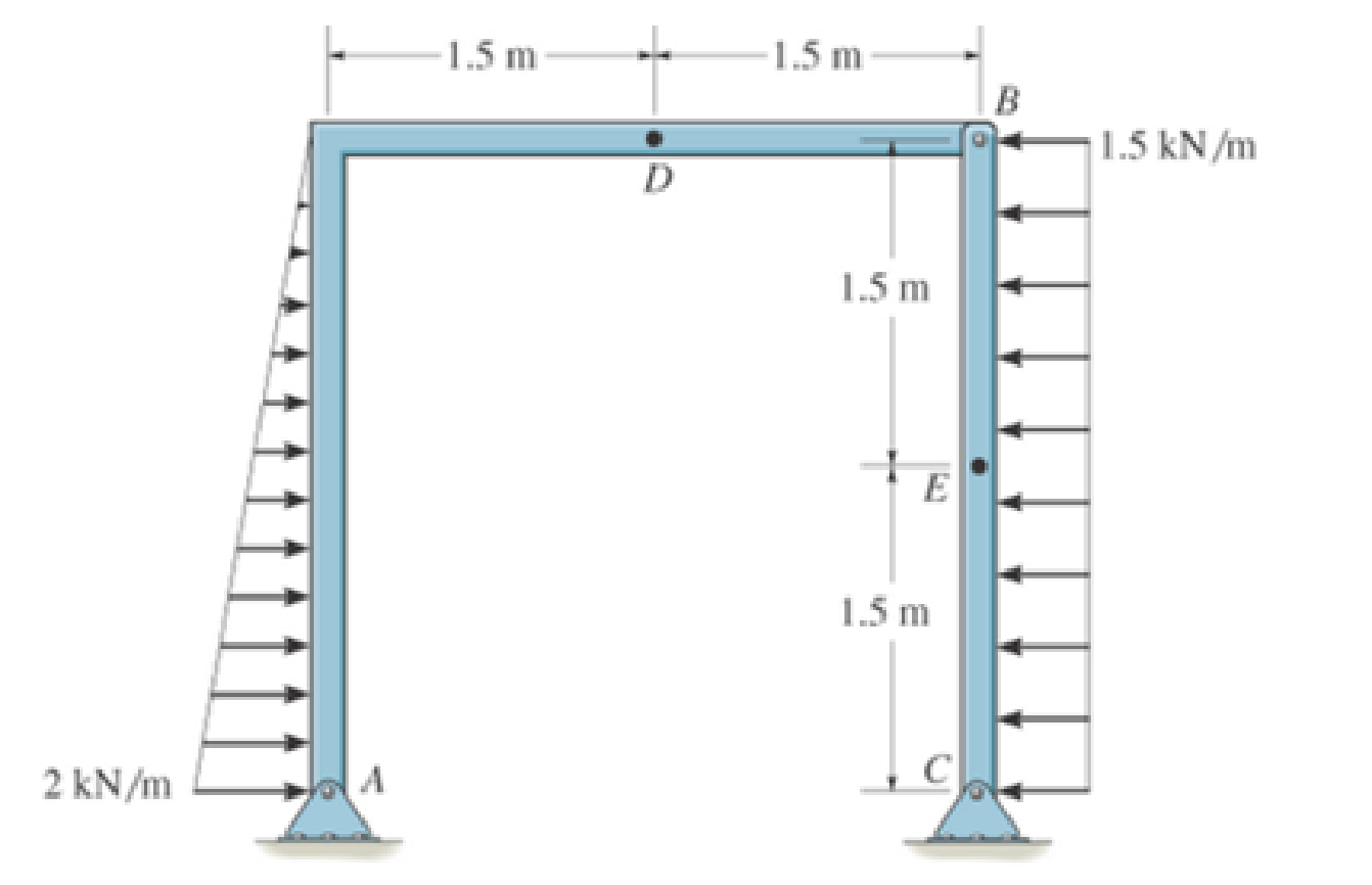
Probs. 7-33/34
Expert Solution & Answer
Want to see the full answer?
Check out a sample textbook solution
Students have asked these similar questions
(read image)
(read image)
(read image)
Chapter 7 Solutions
INTERNATIONAL EDITION---Engineering Mechanics: Statics, 14th edition (SI unit)
Ch. 7.1 - In each case, calculate the reaction at A and then...Ch. 7.1 - Determine the normal force, shear force, and...Ch. 7.1 - Determine the normal force, shear force, and...Ch. 7.1 - Determine the normal force, shear force, and...Ch. 7.1 - Determine the normal force, shear force, and...Ch. 7.1 - Determine the normal force, shear force, and...Ch. 7.1 - Assume A is pinned and B is a roller. Prob. F7-6Ch. 7.1 - Determine the shear force and moment at points C...Ch. 7.1 - Assume the support at B is a roller. Point C is...Ch. 7.1 - Determine the internal normal force, shear force,...
Ch. 7.1 - Determine the internal normal force, shear force,...Ch. 7.1 - If a force of 20 lb is applied to the handles,...Ch. 7.1 - Determine the distance a as a fraction of the...Ch. 7.1 - Determine the internal shear force and moment...Ch. 7.1 - Determine the internal shear force and moment...Ch. 7.1 - Take P = 8 kN. Prob. 7-9Ch. 7.1 - Determine the largest vertical load P the frame...Ch. 7.1 - Determine the internal normal force, shear force,...Ch. 7.1 - Determine the distance a between the bearings in...Ch. 7.1 - Point D is located just to the left of the 5-kip...Ch. 7.1 - The shaft is supported by a journal bearing at A...Ch. 7.1 - Determine the internal normal force, shear force,...Ch. 7.1 - Determine the internal normal force, shear force,...Ch. 7.1 - Determine the normal force, shear force, and...Ch. 7.1 - Determine the internal normal force, shear force,...Ch. 7.1 - Prob. 19PCh. 7.1 - Determine the internal normal force, shear force,...Ch. 7.1 - Point E is located just to the left of 800 N...Ch. 7.1 - Point D is located just to the left of the roller...Ch. 7.1 - Determine the internal normal force, shear force,...Ch. 7.1 - Determine the ratio of a/b for which the shear...Ch. 7.1 - Point E is just to the right of the 3-kip load....Ch. 7.1 - Determine the internal normal force, shear force,...Ch. 7.1 - Determine the internal normal force, shear force,...Ch. 7.1 - Point D is located just to the left of the 10-kN...Ch. 7.1 - Determine the normal force, shear force, and...Ch. 7.1 - Determine the normal force, shear force, and...Ch. 7.1 - Determine the internal normal force, shear force,...Ch. 7.1 - Determine the internal normal force, shear force,...Ch. 7.1 - Determine the internal normal force, shear force,...Ch. 7.1 - Determine the internal normal force, shear force,...Ch. 7.1 - If the suspended load has a weight of 2 kN and a...Ch. 7.1 - Determine the internal normal force, shear force,...Ch. 7.1 - Determine the internal normal force, shear force,...Ch. 7.1 - Determine the internal normal force, shear force,...Ch. 7.1 - The distributed loading W = W0 sin , measured per...Ch. 7.1 - Solve Prob. 7-39 for = 120. Probs. 739/40Ch. 7.1 - z components of force and moment at point C in the...Ch. 7.1 - Determine the x, y, z components of force and...Ch. 7.1 - Determine the x, y, z components of internal...Ch. 7.1 - Determine the x, y. z components of internal...Ch. 7.2 - Determine the shear and moment as a function of x,...Ch. 7.2 - Determine the shear and moment as a function of x,...Ch. 7.2 - Determine the shear and moment as a function of x,...Ch. 7.2 - Determine the shear and moment as a function of x,...Ch. 7.2 - Determine the shear and moment as a function of x,...Ch. 7.2 - Determine the shear and moment as a function of x,...Ch. 7.2 - Draw the shear and moment diagrams for the shaft...Ch. 7.2 - Draw the shear and moment diagrams for the beam...Ch. 7.2 - Draw the shear and moment diagrams for the beam...Ch. 7.2 - Draw the shear and moment diagrams for the...Ch. 7.2 - Draw the shear and moment diagrams of the beam (a)...Ch. 7.2 - If L = 9 m, the beam will fail when the maximum...Ch. 7.2 - Draw the shear and moment diagrams for the beam....Ch. 7.2 - Draw the shear and moment diagrams for the beam....Ch. 7.2 - Draw the shear and bending-moment diagrams for the...Ch. 7.2 - The shaft is supported by a smooth thrust bearing...Ch. 7.2 - Draw the shear and moment diagrams for the beam....Ch. 7.2 - Draw the shear and moment diagrams for the beam....Ch. 7.2 - Draw the shear and moment diagrams for the...Ch. 7.2 - Draw the shear and bending-moment diagrams for...Ch. 7.2 - Draw the shear and moment diagrams for the beam....Ch. 7.2 - The shaft is supported by a smooth thrust bearing...Ch. 7.2 - Draw the shear and moment diagrams for the beam....Ch. 7.2 - The beam will fail when the maximum internal...Ch. 7.2 - Draw the shear and moment diagrams for the beam....Ch. 7.2 - Draw the shear and moment diagrams for the beam....Ch. 7.2 - Draw the shear and moment diagrams for the beam....Ch. 7.2 - Draw the shear and moment diagrams for the beam....Ch. 7.2 - Determine the internal normal force, shear force,...Ch. 7.2 - The quarter circular rod lies in the horizontal...Ch. 7.2 - Express the internal shear and moment components...Ch. 7.3 - Draw the shear and moment diagrams for the beam....Ch. 7.3 - Draw the shear and moment diagrams for the beam....Ch. 7.3 - Draw the shear and moment diagrams for the beam....Ch. 7.3 - Draw the shear and moment diagrams for the beam....Ch. 7.3 - Draw the shear and moment diagrams for the beam....Ch. 7.3 - Draw the shear and moment diagrams for the beam....Ch. 7.3 - Draw the shear and moment diagrams for the beam....Ch. 7.3 - Draw the shear and moment diagrams for the beam....Ch. 7.3 - Draw the shear and moment diagrams for the beam....Ch. 7.3 - Draw the shear and moment diagrams for the...Ch. 7.3 - Draw the shear and moment diagrams for the beam....Ch. 7.3 - Draw the shear and moment diagrams for the beam....Ch. 7.3 - Draw the shear and moment diagrams for the beam....Ch. 7.3 - Draw the shear and moment diagrams for the beam....Ch. 7.3 - Draw the shear and moment diagrams for the beam....Ch. 7.3 - Draw the shear and moment diagrams for the shaft....Ch. 7.3 - Draw the shear and moment diagrams for the beam....Ch. 7.3 - The beam consists of three segments pin connected...Ch. 7.3 - Draw the shear and moment diagrams for the beam....Ch. 7.3 - Draw the shear and moment diagrams for the beam....Ch. 7.3 - Draw the shear and moment diagrams for the beam....Ch. 7.3 - Draw the shear and moment diagrams for the beam....Ch. 7.3 - Draw the shear and moment diagrams for the beam....Ch. 7.3 - Draw the shear and moment diagrams for the beam....Ch. 7.3 - Draw the shear and moment diagrams for the beam....Ch. 7.3 - Draw the shear and moment diagrams for the beam....Ch. 7.3 - Draw the shear and moment diagrams for the beam....Ch. 7.3 - Draw the shear and moment diagrams for the beam....Ch. 7.3 - Draw the shear and moment diagrams for the beam....Ch. 7.3 - Draw the shear and moment diagrams for the beam....Ch. 7.4 - The cable supports the three loads shown....Ch. 7.4 - The cable supports the three loads shown....Ch. 7.4 - Determine the tension in each segment of the cable...Ch. 7.4 - The cable supports the loading shown. Determine...Ch. 7.4 - The cable supports the loading shown. Determine...Ch. 7.4 - The cable supports the three loads shown....Ch. 7.4 - The cable supports the three loads shown....Ch. 7.4 - Determine the force P needed to hold the cable in...Ch. 7.4 - Determine the maximum uniform loading w, measured...Ch. 7.4 - The cable is subjected to a uniform loading of w =...Ch. 7.4 - The cable AB is subjected to a uniform loading of...Ch. 7.4 - Prob. 105PCh. 7.4 - If yB = 1.5 ft. determine the largest weight of...Ch. 7.4 - The cable supports a girder which weighs 850...Ch. 7.4 - Prob. 108PCh. 7.4 - If the pipe has a mass per unit length of 1500...Ch. 7.4 - Prob. 110PCh. 7.4 - Determine the maximum tension developed in the...Ch. 7.4 - Prob. 112PCh. 7.4 - The cable is subjected to the parabolic loading w...Ch. 7.4 - The power transmission cable weighs 10 lb/fl. If...Ch. 7.4 - The power transmission cable weighs 10 lb/ft. If h...Ch. 7.4 - The man picks up the 52-ft chain and holds it just...Ch. 7.4 - Prob. 117PCh. 7.4 - Prob. 118PCh. 7.4 - Prob. 119PCh. 7.4 - A telephone line (cable) stretches between two...Ch. 7.4 - Prob. 121PCh. 7.4 - Prob. 122PCh. 7.4 - A cable has a weight of 5 lb/ft. If it can span...Ch. 7.4 - Prob. 124PCh. 7.4 - Determine the internal normal force, shear force,...Ch. 7.4 - Determine the normal force, shear force, and...Ch. 7.4 - Draw the shear and moment diagrams for the beam....Ch. 7.4 - Draw the shear and moment diagrams for the beam....Ch. 7.4 - Draw the shear and moment diagrams for the beam....Ch. 7.4 - Prob. 6RP
Knowledge Booster


Learn more about
Need a deep-dive on the concept behind this application? Look no further. Learn more about this topic, mechanical-engineering and related others by exploring similar questions and additional content below.Similar questions
- (read me)arrow_forward(read image)arrow_forwardQu. 13 What are the indices for the Direction 2 indicated by vector in the following sketch? Qu. 14 Determine the indices for the direction A and B shown in the following cubic unit cell. please show all work step by step from material engineeringarrow_forward
- The thin-walled open cross section shown is transmitting torque 7. The angle of twist ₁ per unit length of each leg can be determined separately using the equation 01 = 3Ti GLIC 3 where G is the shear modulus, ₁ is the angle of twist per unit length, T is torque, and L is the length of the median line. In this case, i = 1, 2, 3, and T; represents the torque in leg i. Assuming that the angle of twist per unit length for each leg is the same, show that T= Lic³ and Tmaz = G01 Cmax Consider a steel section with Tallow = 12.40 kpsi. C1 2 mm L1 20 mm C2 3 mm L2 30 mm C3 2 mm L3 25 mm Determine the torque transmitted by each leg and the torque transmitted by the entire section. The torque transmitted by the first leg is | N-m. The torque transmitted by the second leg is N-m. The torque transmitted by the third leg is N-m. The torque transmitted by the entire section is N-m.arrow_forwardPlease help, make sure it's to box out and make it clear what answers go where...arrow_forwardThe cylinder floats in the water and oil to the level shown. Determine the weight of the cylinder. (rho)o=910 kg/m^3arrow_forward
- A triangular distributed load of max intensity w acts on beam AB. The beam is supported by a pin at A and member CD, which is connected by pins at C and D respectively. Determine the largest load intensity, Wmax, that can be applied if the pin at D can support a maximum force of 18000 N. Also determine the reactions at A and C and express each answer in Cartesian components. Assume the masses of both beam and member ✓ are negligible. Dwas шал = A BY NC SA 2016 Eric Davishahl C D -a- Ур -b- X B W Values for dimensions on the figure are given in the following table. Note the figure may not be to scale. Variable Value a 6.6 m b 11.88 m C 4.29 m The maximum load intensity is = wmax N/m. The reaction at A is A = The reaction at C is = i+ Ĵ N. ĴN. 12 i+arrow_forwardThe beam is supported by a pin at B and a roller at C and is subjected to the loading shown with w =110 lb/ft, and F 205 lb. a.) If M = 2,590 ft-lb, determine the support reactions at B and C. Report your answers in both Cartesian components. b.) Determine the largest magnitude of the applied couple M for which the beam is still properly supported in equilibrium with the pin and roller as shown. 2013 Michael Swanbom CC BY NC SA M ру W B⚫ C F ka b Values for dimensions on the figure are given in the following table. Note the figure may not be to scale. Variable Value a 3.2 ft b 6.4 ft C 3 ft a.) The reaction at B is B = The reaction at C is C = ĵ lb. i+ Ĵ lb. b.) The largest couple that can be applied is M ft-lb. == i+arrow_forwardThe beam ABC has a mass of 79.0 kg and is supported by the rope BDC that runs through the frictionless pulley at D . The winch at C has a mass of 36.5 kg. The tension in the rope acts on the beam at points B and C and counteracts the moments due to the beam's weight (acting vertically at the midpoint of its length) and the weight of the winch (acting vertically at point C) such that the resultant moment about point A is equal to zero. Assume that rope segment CD is vertical and note that rope segment BD is NOT necessarily perpendicular to the beam. a.) Compute the tension in the rope. b.) Model the two forces the rope exerts on the beam as a single equivalent force and couple moment acting at point B. Enter your answer in Cartesian components. c.) Model the two forces the rope exerts on the beam as a single equivalent force (no couple) and determine the distance from A to the point along the beam where the equivalent force acts (measured parallel to the beam from A ). Enter your answer…arrow_forward
arrow_back_ios
SEE MORE QUESTIONS
arrow_forward_ios
Recommended textbooks for you
 Elements Of ElectromagneticsMechanical EngineeringISBN:9780190698614Author:Sadiku, Matthew N. O.Publisher:Oxford University Press
 Mechanics of Materials (10th Edition)Mechanical EngineeringISBN:9780134319650Author:Russell C. HibbelerPublisher:PEARSON
 Thermodynamics: An Engineering ApproachMechanical EngineeringISBN:9781259822674Author:Yunus A. Cengel Dr., Michael A. BolesPublisher:McGraw-Hill Education
 Control Systems EngineeringMechanical EngineeringISBN:9781118170519Author:Norman S. NisePublisher:WILEY
 Mechanics of Materials (MindTap Course List)Mechanical EngineeringISBN:9781337093347Author:Barry J. Goodno, James M. GerePublisher:Cengage Learning
 Engineering Mechanics: StaticsMechanical EngineeringISBN:9781118807330Author:James L. Meriam, L. G. Kraige, J. N. BoltonPublisher:WILEY
Elements Of Electromagnetics
Mechanical Engineering
ISBN:9780190698614
Author:Sadiku, Matthew N. O.
Publisher:Oxford University Press
Mechanics of Materials (10th Edition)
Mechanical Engineering
ISBN:9780134319650
Author:Russell C. Hibbeler
Publisher:PEARSON
Thermodynamics: An Engineering Approach
Mechanical Engineering
ISBN:9781259822674
Author:Yunus A. Cengel Dr., Michael A. Boles
Publisher:McGraw-Hill Education
Control Systems Engineering
Mechanical Engineering
ISBN:9781118170519
Author:Norman S. Nise
Publisher:WILEY
Mechanics of Materials (MindTap Course List)
Mechanical Engineering
ISBN:9781337093347
Author:Barry J. Goodno, James M. Gere
Publisher:Cengage Learning
Engineering Mechanics: Statics
Mechanical Engineering
ISBN:9781118807330
Author:James L. Meriam, L. G. Kraige, J. N. Bolton
Publisher:WILEY
An Introduction to Stress and Strain; Author: The Efficient Engineer;https://www.youtube.com/watch?v=aQf6Q8t1FQE;License: Standard YouTube License, CC-BY