
Videos
Air enters the evaporator section of a window air conditioner at 100 kPa and 27°C with a volume flow rate of 6 m3/min. The refrigerant-134a at 120 kPa with a quality of 0.3 enters the evaporator at a rate of 2 kg/min and leaves as saturated vapor at the same pressure. Determine the exit temperature of the air and the rate of entropy generation for this process, assuming (a) the outer surfaces of the air conditioner are insulated and (b) heat is transferred to the evaporator of the air conditioner from the surrounding medium at 32°C at a rate of 30 kJ/min.
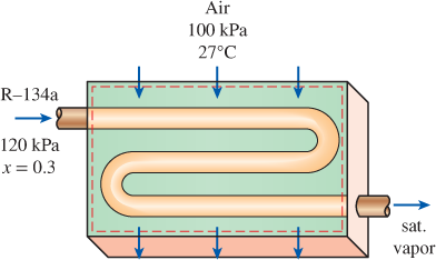
FIGURE P7–180
a)
The exit temperature of air and the entropy generated during the process.
Answer to Problem 181RP
The exit temperature of air is
The entropy generated during the process is
Explanation of Solution
Write the expression to calculate the initial enthalpy of the refrigerant.
Here, initial enthalpy is
Write the expression to calculate the initial entropy of the refrigerant.
Here, initial entropy is
Write the expression to calculate the mass flow rate of air.
Here, mass flow rate of air is
Write the expression for the mass balance of the system.
Here, mass flow rate into the control system is
Write the expression for the energy balance equation for closed system.
Here, rate of energy transfer into the control volume is
Write the expression for the rate of entropy balance for the system.
Here, rate of entropy in the system is
Conclusion:
From Table A-12, “Saturated refrigerant-134a-Pressure table”, Obtain the following properties at saturated pressure of 120 kPa
Saturated liquid enthalpy,
Evaporated enthalpy,
Saturated vapor enthalpy,
Saturated vapor entropy,
Saturated liquid entropy,
Evaporated entropy,
Substitute
Substitute
Refrigerant –134a enters and leaves at the same pressure. Hence,
From Table A-1E, “the molar mass, gas constant and critical–point properties table”, select the gas constant of air at room temperature as
Substitute
Substitute
Here, mass flow rate of refrigerant is
Substitute
Here, mass flow rate of air is
Substitute
From the Table A-2, “Ideal-gas specific heats of various common gases”, select the value of the specific heat at constant pressure value of air as
Substitute 27 C for
Hence, the exit temperature of air is
For the steady flow system, change of entropy in the system is zero.
Substitute
Substitute
Hence, the entropy generated during the process is
b)
The exit temperature of air and the entropy generated during the process.
Answer to Problem 181RP
The exit temperature of air is
The entropy generated during the process is
Explanation of Solution
Write the expression for the energy balance equation for closed system.
Here, rate of energy transfer into the control volume is
Write the expression for the rate of entropy balance for the system.
Here, rate of entropy in the system is
Conclusion:
Substitute
Here, rate of heat gain from the surrounding is
Substitute 27 C for
Hence, the exit temperature of air is
For the steady flow system, change of entropy in the system is zero.
Substitute
Substitute
Hence, the entropy generated during the process is
Want to see more full solutions like this?
Chapter 7 Solutions
EBK THERMODYNAMICS: AN ENGINEERING APPR


- Correct Answer is written below. Detailed and complete fbd only please. I will upvote, thank you. 1: The assembly shown is composed of a rigid plank ABC, supported by hinge at A, spring at B and cable at C.The cable is attached to a frictionless pulley at D and rigidly supported at E. The cable is made of steel with E = 200,000MPa and cross-sectional area of 500 mm2. The details of pulley at D is shown. The pulley is supported by a pin, passingthough the pulley and attached to both cheeks. Note that E is directly above B.Given: H = 3 m; L1 = 2 m; L2 = 4 m; w = 12 kN/m; x:y = 3:4Spring Parameters:Wire diameter = 30 mmMean Radius = 90 mmNumber of turns = 12Modulus of Rigidity = 80 GPaAllowable stresses:Allowable shear stress of Pin at D = 85 MPaAllowable normal stress of cheek at D = 90MPaAllowable bearing stress of cheek at D = 110MPa1. Calculate the reaction of spring Band tension in cable at C.2. Calculate the vertical displacementat C and the required diameter ofpin at D.3.…arrow_forwardCorrect answer and complete fbd only. I will upvote. The compound shaft, composed of steel,aluminum, and bronze segments, carries the two torquesshown in the figure. If TC = 250 lb-ft, determine the maximumshear stress developed in each material (in ksi). The moduliof rigidity for steel, aluminum, and bronze are 12 x 106 psi, 4x 10⁶ psi, and 6 x 10⁶ psi, respectivelyarrow_forwardCan you explain the algebra steps that aren't shown but stated to be there, on how to get this equationarrow_forward
- Correct answer and complete fbd only. I will upvote. A flanged bolt coupling consists of two concentric rows of bolts. The inner row has 6 nos. of 16mm diameterbolts spaced evenly in a circle of 250mm in diameter. The outer row of has 10 nos. of 25 mm diameter bolts spaced evenly in a circle of 500mm in diameter. If the allowable shear stress on one bolt is 60 MPa, determine the torque capacity of the coupling. The Poisson’s ratio of the inner row of bolts is 0.2 while that of the outer row is 0.25 and the bolts are steel, E =200 GPa.arrow_forwardCorrect answer and complete fbd only. I will upvote. 10: The constant wall thickness of a steel tube with the cross sectionshown is 2 mm. If a 600-N-m torque is applied to the tube. Use G = 80 GPa forsteel.1. Find the shear stress (MPa) in the wall of the tube.2. Find the angle of twist, in degrees per meter of length.arrow_forwardCORRECT ANSWER WITH COMPLETE FBD ONLY. I WILL UPVOTE. A torque wrench is used to tighten the pipe shown.Dimensions: S1 = 400 mm; S2 = 250 mm; S3 = 100 mmModulus of Rigidity G = 78 GPa1. The diameter of the solid pipe is 20 mm. How much is themaximum force P (N) that can be applied based on theallowable shear stress of 60 MPa?2. For a hollow pipe with 50 mm outside diameter and is 6 mmthick, compute for the maximum force P (kN) that can beapplied such that the angle of twist at A does not exceed 5degrees.3. The torque applied to tighten the hollow pipe is 200 N-m.Given: Pipe outside diameter = 50 mm Pipe thickness = 6 mmSolve for the resulting maximum shear stress (MPa) in the pipe.arrow_forward
- Correct answer and complete fbd only. I will upvote. 6: The shaft carries a total torque T0 that is uniformly distributedover its length L. Determine the angle of twist (degrees) of the shaft in termsif T0 = 1.2 kN-m, L = 2 m, G = 80 GPa, and diameter = 120 mm.arrow_forward2. Calculate the force in all members of the trusses shown using the method of joints. A 5525 lb C 3500 lb BY 14'-0" D 10'- 0" 6250 lb 10'- 0" Earrow_forwardCorrect answer and complete fbd only. I will upvote. 8: The steel rod fits loosely inside the aluminum sleeve. Both components are attached to a rigid wall at A andjoined together by a pin at B. Because of a slight misalignmentof the pre-drilled holes, the torque T0 = 750 N-m was appliedto the steel rod before the pin could be inserted into theholes. Determine the torque (N-m) in each component afterT0 was removed. Use G = 80 GPa for steel and G = 28 GPa foraluminumarrow_forward
- Correct answer and complete fbd only. I will upvote. 9: The two steel shafts, each with one end builtinto a rigid support, have flanges attached to their freeends. The flanges are to be bolted together. However,initially there is a 6⁰ mismatch in the location of the boltholes as shown in the figure. Determine the maximumshear stress(ksi) in each shaft after the flanges have beenbolted together. The shear modulus of elasticity for steelis 12 x 106 psi. Neglect deformations of the bolts and theflanges.arrow_forwardCorrect answer and complete fbd only. I will upvote. The tapered, wrought iron shaft carriesthe torque T = 2000 lb-in at its free end. Determine theangle of twist (degrees) of the shaft. Use G = 10 x 106psi for wrought ironarrow_forwardCorrect answer and complete fbd only. I will upvote. The compound shaft, consisting of steel and aluminumsegments, carries the two torques shown in the figure. Determine themaximum permissible value of T subject to the following designconditions: τst ≤ 83 MPa, τal ≤ 55 MPa, and θ ≤ 6⁰ (θ is the angle ofrotation of the free end). Use G =83 GPa for steel and G = 28 GPa foraluminum.arrow_forward
 Elements Of ElectromagneticsMechanical EngineeringISBN:9780190698614Author:Sadiku, Matthew N. O.Publisher:Oxford University Press
 Mechanics of Materials (10th Edition)Mechanical EngineeringISBN:9780134319650Author:Russell C. HibbelerPublisher:PEARSON
 Thermodynamics: An Engineering ApproachMechanical EngineeringISBN:9781259822674Author:Yunus A. Cengel Dr., Michael A. BolesPublisher:McGraw-Hill Education
 Control Systems EngineeringMechanical EngineeringISBN:9781118170519Author:Norman S. NisePublisher:WILEY
 Mechanics of Materials (MindTap Course List)Mechanical EngineeringISBN:9781337093347Author:Barry J. Goodno, James M. GerePublisher:Cengage Learning
 Engineering Mechanics: StaticsMechanical EngineeringISBN:9781118807330Author:James L. Meriam, L. G. Kraige, J. N. BoltonPublisher:WILEY