Videos
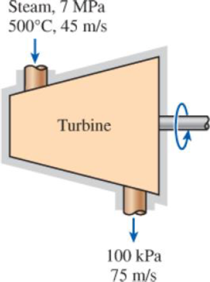
Steam enters an adiabatic turbine steadily at 7 MPa, 500°C, and 45 m/s and leaves at 100 kPa and 75 m/s. If the power output of the turbine is 5 MW and the isentropic efficiency is 77 percent, determine (a) the mass flow rate of steam through the turbine, (b) the temperature at the turbine exit, and (c) the rate of entropy generation during this process.
FIGURE P7–137
a)
The mass flow rate of the steam.
Answer to Problem 137P
The mass flow rate of the steam is
Explanation of Solution
Write the expression for the energy balance equation for closed system.
Here, rate of net energy transfer in to the control volume is
Write the expression to calculate the power output for the isentropic process.
Here, the power output for the isentropic process is
Conclusion:
The rate of change in internal energy of the system is zero at steady state.
Substitute 0 for
Here, mass flow rate is
From the Table A-6, “superheated water table”, select the initial enthalpy
The entropy remains constant since the process is isentropic
From the Table A-6, “superheated water table”, select the enthalpy at final state in isentropic process
Substitute 5,000 kW for
Substitute
Thus, the mass flow rate of the steam is
b)
The exit temperature of the steam.
Answer to Problem 137P
The exit temperature of the steam is
Explanation of Solution
Write the expression to calculate the mass flow rate of the steam.
Here, rate of actual work is
Conclusion:
Substitute
From the Table A-6, “superheated water table”, obtain final entropy at pressure of
From the Table A-6, “Superheated water”, obtain the value of exit temperature
Write the formula of interpolation method of two variables.
Here, the variables denoted by x and y are exit temperature and enthalpy.
Show exit temperature and enthalpy values from the Table A-6.
| Temperature | Enthalpy |
| 2675 | 100 |
| 2683.5 | ? |
| 2776.6 | 150 |
Substitute
The value of exit temperature
Thus, the exit temperature of the steam is
c)
The entropy generation in the turbine.
Answer to Problem 137P
The entropy generation in the turbine is
Explanation of Solution
Write the expression to calculate the entropy generation in the turbine.
Here, entropy generation in the turbine is
Conclusion:
Substitute
Thus, the entropy generation in the turbine is
Want to see more full solutions like this?
Chapter 7 Solutions
EBK THERMODYNAMICS: AN ENGINEERING APPR


- This is an exam review question. The answer is Pmin = 622.9 lb but whyarrow_forwardPlease do not use any AI tools to solve this question. I need a fully manual, step-by-step solution with clear explanations, as if it were done by a human tutor. No AI-generated responses, please.arrow_forwardPlease do not use any AI tools to solve this question. I need a fully manual, step-by-step solution with clear explanations, as if it were done by a human tutor. No AI-generated responses, please.arrow_forward
- Please do not use any AI tools to solve this question. I need a fully manual, step-by-step solution with clear explanations, as if it were done by a human tutor. No AI-generated responses, please.arrow_forwardThis is an old practice exam. Fce = 110lb and FBCD = 62 lb but whyarrow_forwardQuiz/An eccentrically loaded bracket is welded to the support as shown in Figure below. The load is static. The weld size for weld w1 is h1 = 4mm, for w2 h2 = 6mm, and for w3 is h3 =6.5 mm. Determine the safety factor (S.f) for the welds. F=29 kN. Use an AWS Electrode type (E100xx). 163 mm S 133 mm 140 mm Please solve the question above I solved the question but I'm sure the answer is wrong the link : https://drive.google.com/file/d/1w5UD2EPDiaKSx3W33aj Rv0olChuXtrQx/view?usp=sharingarrow_forward
- Q2: (15 Marks) A water-LiBr vapor absorption system incorporates a heat exchanger as shown in the figure. The temperatures of the evaporator, the absorber, the condenser, and the generator are 10°C, 25°C, 40°C, and 100°C respectively. The strong liquid leaving the pump is heated to 50°C in the heat exchanger. The refrigerant flow rate through the condenser is 0.12 kg/s. Calculate (i) the heat rejected in the absorber, and (ii) the COP of the cycle. Yo 8 XE-V lo 9 Pc 7 condenser 5 Qgen PG 100 Qabs Pe evaporator PRV 6 PA 10 3 generator heat exchanger 2 pump 185 absorberarrow_forwardQ5:(? Design the duct system of the figure below by using the balanced pressure method. The velocity in the duct attached to the AHU must not exceed 5m/s. The pressure loss for each diffuser is equal to 10Pa. 100CFM 100CFM 100CFM ☑ ☑ 40m AHU -16m- 8m- -12m- 57m 250CFM 40m -14m- 26m 36m ☑ 250CFMarrow_forwardA mass of ideal gas in a closed piston-cylinder system expands from 427 °C and 16 bar following the process law, pv1.36 = Constant (p times v to the power of 1.36 equals to a constant). For the gas, initial : final pressure ratio is 4:1 and the initial gas volume is 0.14 m³. The specific heat of the gas at constant pressure, Cp = 0.987 kJ/kg-K and the specific gas constant, R = 0.267 kJ/kg.K. Determine the change in total internal energy in the gas during the expansion. Enter your numerical answer in the answer box below in KILO JOULES (not in Joules) but do not enter the units. (There is no expected number of decimal points or significant figures).arrow_forward
- my ID# 016948724. Please solve this problem step by steparrow_forwardMy ID# 016948724 please find the forces for Fx=0: fy=0: fz=0: please help me to solve this problem step by steparrow_forwardMy ID# 016948724 please solve the proble step by step find the forces fx=o: fy=0; fz=0; and find shear moment and the bending moment diagran please draw the diagram for the shear and bending momentarrow_forward
 Refrigeration and Air Conditioning Technology (Mi...Mechanical EngineeringISBN:9781305578296Author:John Tomczyk, Eugene Silberstein, Bill Whitman, Bill JohnsonPublisher:Cengage Learning
 Principles of Heat Transfer (Activate Learning wi...Mechanical EngineeringISBN:9781305387102Author:Kreith, Frank; Manglik, Raj M.Publisher:Cengage Learning