
VECTOR MECH....F/ENGNRS-STATICS -CONNECT
12th Edition
ISBN: 9781260689495
Author: BEER
Publisher: MCG CUSTOM
expand_more
expand_more
format_list_bulleted
Videos
Textbook Question
Chapter 7.1, Problem 7.9P
A semicircular rod is loaded as shown. Determine the internal forces at point J.
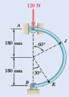
Fig. P7.9 and P7.10
Expert Solution & Answer
Want to see the full answer?
Check out a sample textbook solution
Students have asked these similar questions
This problem illustrates that the factor of safety for a machine element depends on the particular point selected for
analysis. Here you are to compute factors of safety, based upon the distortion-energy theory, for stress elements at A and
B of the member shown in the figure. This bar is made of AISI 1006 cold-drawn steel and is loaded by the forces
F = 1.100 kN, P = 8.00 kN, and T = 50.00 N-m. Given: Sy = 280 MPa.
B
-100 mm-
15-mm D.
a) Determine the value of the axial stress at point B.
b) Determine the value of the shear stress at point B.
c) Determine the value of the Von Mises stress at
point B.
P
F
A piston-cylinder device initially contains 0.08 m^3 of nitrogen gas at 130
kPa and 170°C. The nitrogen is expanded to a pressure of 80 kPa via
isentropic expansion. Determine the final temperature and the boundary
work done by the system during this process.
A Carnot (ideal) heat pump is to be used to heat a house and maintain it at 22°C
in winter. On a day when the average outdoor temperature remains at about 0°C,
the house is estimated to lose heat at a rate of 65,000 kJ/h. If the heat pump
consumes 6 kW of power while operating, determine:
(a) how long the heat pump ran on that day
(b) the total heating costs, assuming an average price of 11¢/kWh for electricity
(c) the heating cost for the same day if an 85% efficient electric furnace is used
instead of a heat pump.
Chapter 7 Solutions
VECTOR MECH....F/ENGNRS-STATICS -CONNECT
Ch. 7.1 - 7.1 and 7.2 Determine the internal forces (axial...Ch. 7.1 - Prob. 7.2PCh. 7.1 - Determine the internal forces at point J when =...Ch. 7.1 - Fig. P7.3 and P7.4 7.4 Determine the internal...Ch. 7.1 - Determine the internal forces at point J when =...Ch. 7.1 - Fig. P7.5 and P7.6 7.6 Determine the internal...Ch. 7.1 - An archer aiming at a target is pulling with a...Ch. 7.1 - For the bow of Prob. 7.7, determine the magnitude...Ch. 7.1 - A semicircular rod is loaded as shown. Determine...Ch. 7.1 - A semicircular rod is loaded as shown. Determine...
Ch. 7.1 - A semicircular rod is loaded as shown. Determine...Ch. 7.1 - Fig. P7.11 and P7.12 7.12 A semicircular rod is...Ch. 7.1 - The axis of the curved member AB is a parabola...Ch. 7.1 - Knowing that the axis of the curved member AB is a...Ch. 7.1 - Knowing that the radius of each pulley is 120 mm...Ch. 7.1 - Fig. P7.15 and P7.16 7.16 Knowing that the radius...Ch. 7.1 - A 5-in.-diameter pipe is supported every 9 ft by a...Ch. 7.1 - For the frame of Prob. 7.17, determine the...Ch. 7.1 - Knowing that the radius of each pulley is 200 mm...Ch. 7.1 - Fig. P7.19 and P7.20 7.20 Knowing that the radius...Ch. 7.1 - and 7.22 A force P is applied to a bent rod that...Ch. 7.1 - and 7.22 A force P is applied to a bent rod that...Ch. 7.1 - A quarter-circular rod of weight W and uniform...Ch. 7.1 - For the rod of Prob. 7.23, determine the magnitude...Ch. 7.1 - A semicircular rod of weight W and uniform cross...Ch. 7.1 - A semicircular rod of weight W and uniform cross...Ch. 7.1 - 7.27 and 7.28 A half section of pipe rests on a...Ch. 7.1 - 7.27 and 7.28 A half section of pipe rests on a...Ch. 7.2 - 7.29 through 7.32 For the beam and loading shown,...Ch. 7.2 - 7.29 through 7.32 For the beam and loading shown,...Ch. 7.2 - 7.29 through 7.32 For the beam and loading shown,...Ch. 7.2 - 7.29 through 7.32 For the beam and loading shown,...Ch. 7.2 - 7.33 and 7.34 For the beam and loading shown, (a)...Ch. 7.2 - 7.33 and 7.34 For the beam and loading shown, (a)...Ch. 7.2 - 7.35 and 7.36 For the beam and loading shown, (a)...Ch. 7.2 - 7.35 and 7.36 For the beam and loading shown, (a)...Ch. 7.2 - 7.37 and 7.38 For the beam and loading shown, (a)...Ch. 7.2 - 7.37 and 7.38 For the beam and loading shown, (a)...Ch. 7.2 - For the beam and loading shown, (a) draw the shear...Ch. 7.2 - For the beam and loading shown, (a) draw the shear...Ch. 7.2 - For the beam and loading shown, (a) draw the shear...Ch. 7.2 - For the beam and loading shown, (a) draw the shear...Ch. 7.2 - Assuming the upward reaction of the ground on beam...Ch. 7.2 - Solve Problem 7.43 knowing that P = 3wa. PROBLEM...Ch. 7.2 - Assuming the upward reaction of the ground on beam...Ch. 7.2 - Solve Prob. 7.45 assuming that the 12-kip load has...Ch. 7.2 - Assuming the upward reaction of the ground on beam...Ch. 7.2 - Prob. 7.48PCh. 7.2 - Draw the shear and bending-moment diagrams for the...Ch. 7.2 - Draw the shear and bending-moment diagrams for the...Ch. 7.2 - Draw the shear and bending-moment diagrams for the...Ch. 7.2 - Draw the shear and bending-moment diagrams for the...Ch. 7.2 - Two small channel sections DF and EH have been...Ch. 7.2 - Solve Prob. 7.53 when = 60. PROBLEM 7.53 Two...Ch. 7.2 - For the structural member of Prob. 7.53, determine...Ch. 7.2 - For the beam of Prob. 7.43, determine (a) the...Ch. 7.2 - Determine (a) the distance a for which the maximum...Ch. 7.2 - For the beam and loading shown, determine (a) the...Ch. 7.2 - A uniform beam is to be picked up by crane cables...Ch. 7.2 - Knowing that P = Q = 150 lb, determine (a) the...Ch. 7.2 - Knowing that P = Q = 150 lb, determine (a) the...Ch. 7.2 - In order to reduce the bending moment in the...Ch. 7.3 - Using the method of Sec. 7.3, solve Prob. 7.29....Ch. 7.3 - Prob. 7.64PCh. 7.3 - Using the method of Sec. 7.3, solve Prob. 7.31....Ch. 7.3 - Prob. 7.66PCh. 7.3 - Using the method of Sec. 7.3, solve Prob. 7.33....Ch. 7.3 - Using the method of Sec. 7.3, solve Prob. 7.34....Ch. 7.3 - 7.69 and 7.70 For the beam and loading shown, (a)...Ch. 7.3 - 7.69 and 7.70 For the beam and loading shown, (a)...Ch. 7.3 - Using the method of Sec. 7.3, solve Prob. 7.39....Ch. 7.3 - Using the method of Sec. 7.3, solve Prob. 7.40....Ch. 7.3 - Using the method of Sec. 7.3, solve Prob. 7.41....Ch. 7.3 - Using the method of Sec. 7.3, solve Prob. 7.42....Ch. 7.3 - 7.75 and 7.76 For the beam and loading shown, (a)...Ch. 7.3 - Prob. 7.76PCh. 7.3 - For the beam and loading shown, (a) draw the shear...Ch. 7.3 - For the beam and loading shown, (a) draw the shear...Ch. 7.3 - For the beam and loading shown, (a) draw the shear...Ch. 7.3 - For the beam and loading shown, (a) draw the shear...Ch. 7.3 - For the beam and loading shown, (a) draw the shear...Ch. 7.3 - For the beam and loading shown, (a) draw the shear...Ch. 7.3 - (a) Draw the shear and bending-moment diagrams for...Ch. 7.3 - Solve Prob. 7.83 assuming that the 300-lb force...Ch. 7.3 - For the beam and loading shown, (a) write the...Ch. 7.3 - For the beam and loading shown, (a) write the...Ch. 7.3 - For the beam and loading shown, (a) write the...Ch. 7.3 - For the beam and loading shown, (a) write the...Ch. 7.3 - The beam AB supports the uniformly distributed...Ch. 7.3 - Solve Prob. 7.89 assuming that the uniformly...Ch. 7.3 - The beam AB is subjected to the uniformly...Ch. 7.3 - Prob. 7.92PCh. 7.4 - Three loads are suspended as shown from the cable...Ch. 7.4 - Knowing that the maximum tension in cable ABCDE is...Ch. 7.4 - If dA = 8 ft and dc = 10 ft, determine the...Ch. 7.4 - Prob. 7.96PCh. 7.4 - Knowing that dc = 5 m, determine (a) the distances...Ch. 7.4 - Prob. 7.98PCh. 7.4 - Knowing that dc = 9 ft, determine (a) the...Ch. 7.4 - Prob. 7.100PCh. 7.4 - Knowing that mB = 70 kg and mC = 25 kg, determine...Ch. 7.4 - Fig. P7.101 and P7.102 7.102 Knowing that mB = 18...Ch. 7.4 - Cable ABC supports two loads as shown. Knowing...Ch. 7.4 - Prob. 7.104PCh. 7.4 - If a = 3 m, determine the magnitudes of P and Q...Ch. 7.4 - If a = 4 m, determine the magnitudes of P and Q...Ch. 7.4 - An electric wire having a mass per unit length of...Ch. 7.4 - The total mass of cable ACB is 20 kg. Assuming...Ch. 7.4 - The center span of the George Washington Bridge,...Ch. 7.4 - The center span of the Verrazano-Narrows Bridge...Ch. 7.4 - Each cable of the Golden Gate Bridge supports a...Ch. 7.4 - Two cables of the same gauge are attached to a...Ch. 7.4 - A 76-m length of wire having a mass per unit...Ch. 7.4 - A cable of length L + is suspended between two...Ch. 7.4 - The total mass of cable AC is 25 kg. Assuming that...Ch. 7.4 - Cable ACB supports a load uniformly distributed...Ch. 7.4 - Each cable of the side spans of the Golden Gate...Ch. 7.4 - A steam pipe weighing 45 lb/ft that passes between...Ch. 7.4 - A cable AB of span L and a simple beam AB of the...Ch. 7.4 - Making use of the property established in Prob....Ch. 7.4 - 7.120 through 7.123 Making use of the property...Ch. 7.4 - 7.120 through 7.123 Making use of the property...Ch. 7.4 - Prob. 7.123PCh. 7.4 - Prob. 7.124PCh. 7.4 - Using the property indicated in Prob. 7.124,...Ch. 7.4 - If the weight per unit length of the cable AB is...Ch. 7.5 - A 25-ft chain with a weight of 30 lb is suspended...Ch. 7.5 - A 500-ft-long aerial tramway cable having a weight...Ch. 7.5 - A 40-m cable is strung as shown between two...Ch. 7.5 - A 50-m steel surveying tape has a mass of 1.6 kg....Ch. 7.5 - Prob. 7.131PCh. 7.5 - Prob. 7.132PCh. 7.5 - A 20-m length of wire having a mass per unit...Ch. 7.5 - Determine the sag of a 30-ft chain that is...Ch. 7.5 - Prob. 7.135PCh. 7.5 - Prob. 7.136PCh. 7.5 - A cable weighing 2 lb/ft is suspended between two...Ch. 7.5 - Prob. 7.138PCh. 7.5 - Prob. 7.139PCh. 7.5 - Fig. P7.139 and P7.140 7.140 A motor M is used to...Ch. 7.5 - Prob. 7.141PCh. 7.5 - Prob. 7.142PCh. 7.5 - Prob. 7.143PCh. 7.5 - Prob. 7.144PCh. 7.5 - To the left of point B, the long cable ABDE rests...Ch. 7.5 - Fig. P7.145 and P7.146 7.146 To the left of point...Ch. 7.5 - The 10-ft cable AB is attached to two collars as...Ch. 7.5 - Prob. 7.148PCh. 7.5 - Prob. 7.149PCh. 7.5 - (a) Determine the maximum allowable horizontal...Ch. 7.5 - A cable has a mass per unit length of 3 kg/m and...Ch. 7.5 - Determine the sag-to-span ratio for which the...Ch. 7.5 - Prob. 7.153PCh. 7 - Knowing that the turnbuckle has been tightened...Ch. 7 - Knowing that the turnbuckle has been tightened...Ch. 7 - Two members, each consisting of a straight and a...Ch. 7 - Knowing that the radius of each pulley is 150 mm,...Ch. 7 - For the beam shown, determine (a) the magnitude P...Ch. 7 - For the beam and loading shown, (a) draw the shear...Ch. 7 - For the beam and loading shown, (a) draw the shear...Ch. 7 - For the beam shown, draw the shear and...Ch. 7 - The beam AB, which lies on the ground, supports...Ch. 7 - Two loads are suspended as shown from the cable...Ch. 7 - A wire having a mass per unit length of 0.65 kg/m...Ch. 7 - A 10-ft rope is attached to two supports A and B...
Knowledge Booster


Learn more about
Need a deep-dive on the concept behind this application? Look no further. Learn more about this topic, mechanical-engineering and related others by exploring similar questions and additional content below.Similar questions
- From the information in the image, I needed to find the orientation of U relative to Q in vector basis q_hat. I transformed the euler angle/axis representation to euler parameters. Then I got its conjugate in order to get the euler parameter in N frame relative to Q. The problem gave the euler angle/axis representation in Q frame relative to N, so I needed to find the conjugate. Then I used the euler parameter rule of successive rotation to find the final euler parameters that describe the orientation of U relative to Q. However that orientation is in n_hat which is the intermediate frame. How do I get the final result in q_hat?arrow_forwardA proposed method of power generation involves collecting and storing solar energy in large artificial lakes a few meters deep, called solar ponds. Solar energy is absorbed by all parts of the pond, and the water temperature rises everywhere. The top part of the pond, however, loses much of the heat it absorbs to the atmosphere, and as a result, the cool surface water serves as insulation for the bottom part of the pond and helps trap the energy there. Usually, salt is planted at the bottom of the pond to prevent the rise of this hot water to the top. A heat engine that uses an organic fluid, such as alcohol, as the working fluid can be operated between the top and the bottom portions of the pond. If the water temperature is 27°C near the surface and 72°C near the bottom of the pond, determine the maximum thermal efficiency that this power plant can have. Treat the cycle as an ideal heat engine. Would a heat engine operating under these temperature conditions (27°C and 72°C) be…arrow_forwardA standard Carnot heat engine cycle is executed in a closed system between the temperature limits of 320 and 1350 K, with air as the working fluid. The pressures before and after the isothermal compression are 150 and 300 kPa, respectively. Sketch the TS diagram for this cycle. If the net work output per cycle is 0.75 kJ, determine the efficiency of the cycle and the heat transfer to the air (working fluid) per cycle.arrow_forward
- PROBLEM 10: A sleeve in the form of a circular tube of length L is Nut placed around a bolt and fitted between washers at each end. The nut is then turned until it is just snug. Use material properties as follows: For the sleeve, as = 21 x 106/°C and Es = 100 GPa Washer Bolt ·L· Sleeve Bolt head For the bolt, αB = 10 × 10-6/°C and EB = 200 GPa. 1. Calculate the temperature rise that is required to produce a compressive stress of 25 MPa in the sleeve.arrow_forwardThis problem illustrates that the factor of safety for a machine element depends on the particular point selected for analysis. Here you are to compute factors of safety, based upon the distortion-energy theory, for stress elements at A and B of the member shown in the figure. This bar is made of AISI 1006 cold-drawn steel and is loaded by the forces F = 1.100 kN, P = 8.00 kN, and T = 50.00 N·m. Given: Sy = 280 MPa. B -100 mm- 15-mm D. a) What is the value of the axial stress at point A? b)What is the value of the shear stress at point A? c)Determine the value of the Von Mises stress at point A. P Farrow_forwardThe three steel wires, each of cross-sectional area 0.05 in2, support the weight W. Theirunstressed lengths are 74.98 ft, 74.99 ft, and 75.00 ft. Use E = 29 x 106 psi.1. Find the stress (psi) in the longest wire if W = 1500 lb.2. Determine the stress in the shortest wire if W = 500 lb ANSWERS: 6130 psi; 6930 psiarrow_forward
- 1: The concrete column is reinforced using four steel reinforcing rods, each having a diameter of 18 mm. Determine the stress in the concrete and the steel if the column is subjected to an axial load of 800 kN. Est = 200 GPa, Ec = 25 GPa. Complete fbd.arrow_forward5: As shown, two aluminum rods AB and BC, hinged to rigid supports, arepinned together at B to carry a vertical load P = 6000 lb. If each rod has a crosssectional area of 0.60 in2 and E = 10 x 106 psi. Use α = θ = 30⁰. Calculate the change in length (in) of rod AB and indicate if it elongates orshortens. Calculate the vertical displacement of B (in) and horizontal displacement of B (in). Complete fbd.arrow_forward2: The rigid bar supports the uniform distributedload of 6 kip/ft. Determine the force in each cable if each cable has a cross-sectional area of 0.05 in^2 , and E = 31(10)^3 ksi.arrow_forward
- In (Figure 1), take m₁ = 4 kg and mB = 4.6 kg. Determine the z component of the angular momentum Ho of particle A about point O. Determine the z component of the angular momentum Ho of particle B about point O. Suppose that 5 m 8 m/s 4 m 1.5 m 4 m B MB 1 m 2 m 5 30° 6 m/s MAarrow_forwardThe two disks A and B have a mass of 4 kg and 6 kg, respectively. They collide with the initial velocities shown. The coefficient of restitution is e = 0.75. Suppose that (VA)1 = 6 m/s, (VB)₁ = 7 m/s. (Figure 1) Determine the magnitude of the velocity of A just after impact. Determine the angle between the x axis and the velocity of A just after impact, measured clockwise from the negative x axis. Determine the magnitude of the velocity of B just after impact. Determine the angle between the x axis and the velocity of B just after impact, measured clockwise from the positive x axis. (VB)1 B (VA)1 60° Line of impactarrow_forwardA hot plane surface is maintained at 100°C, and it is exposed to air at 25°C.The combined heat transfer coefficient between the surface and the air is 25W/m²·K. (same as above). In this task, you are asked to design fins to cool asurface by attaching 3 cm-long, 0.25 cm-diameter aluminum pin fins (thermalconductivity, k = 237 W/m·K) with a center-to-center distance of 0.6 cm. (Tip:do not correct the length). Determine the rate of heat transfer from thefinned structure to the air for a 1 m x 1 m section of the plate.arrow_forward
arrow_back_ios
SEE MORE QUESTIONS
arrow_forward_ios
Recommended textbooks for you
 Elements Of ElectromagneticsMechanical EngineeringISBN:9780190698614Author:Sadiku, Matthew N. O.Publisher:Oxford University Press
 Mechanics of Materials (10th Edition)Mechanical EngineeringISBN:9780134319650Author:Russell C. HibbelerPublisher:PEARSON
 Thermodynamics: An Engineering ApproachMechanical EngineeringISBN:9781259822674Author:Yunus A. Cengel Dr., Michael A. BolesPublisher:McGraw-Hill Education
 Control Systems EngineeringMechanical EngineeringISBN:9781118170519Author:Norman S. NisePublisher:WILEY
 Mechanics of Materials (MindTap Course List)Mechanical EngineeringISBN:9781337093347Author:Barry J. Goodno, James M. GerePublisher:Cengage Learning
 Engineering Mechanics: StaticsMechanical EngineeringISBN:9781118807330Author:James L. Meriam, L. G. Kraige, J. N. BoltonPublisher:WILEY
Elements Of Electromagnetics
Mechanical Engineering
ISBN:9780190698614
Author:Sadiku, Matthew N. O.
Publisher:Oxford University Press
Mechanics of Materials (10th Edition)
Mechanical Engineering
ISBN:9780134319650
Author:Russell C. Hibbeler
Publisher:PEARSON
Thermodynamics: An Engineering Approach
Mechanical Engineering
ISBN:9781259822674
Author:Yunus A. Cengel Dr., Michael A. Boles
Publisher:McGraw-Hill Education
Control Systems Engineering
Mechanical Engineering
ISBN:9781118170519
Author:Norman S. Nise
Publisher:WILEY
Mechanics of Materials (MindTap Course List)
Mechanical Engineering
ISBN:9781337093347
Author:Barry J. Goodno, James M. Gere
Publisher:Cengage Learning
Engineering Mechanics: Statics
Mechanical Engineering
ISBN:9781118807330
Author:James L. Meriam, L. G. Kraige, J. N. Bolton
Publisher:WILEY
How to balance a see saw using moments example problem; Author: Engineer4Free;https://www.youtube.com/watch?v=d7tX37j-iHU;License: Standard Youtube License