Interpretation:
The shaft design using the appropriate material for given condition should be determined.
Concept introduction:
Endurance strength is the value of maxium reveresed bending stress that a material can withstand without failure for finite number of cycle.
The following condition are specified based on number of cycle, If number of cycles are more than
Endurance Ratio:
It is defined as the ratio of endurance limit to tensile strength, the relationship is given below:
It helps to estimate the properties of fatigue using tensile test. The value of endurance limit for metallic material is 0.3 to 0.4.
Relationship for endurance limit is shown below:
Where,
F is the applied load in pounds.
L is the length I inch.
D is the diameter in inch.
Answer to Problem 7.66DP
Magnesium-Manganese alloy is best suitable material for shaft designing based on the value of fatigue strength.
Explanation of Solution
Given Information:
The value of load is
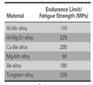
The material used along with the values of fatigue strength is shown in table below:

The required values are shown in table,
The relationship for Endurance limit is,
Considering the case for Aluminum manganese alloy,
The amount of load applied is
The value of fatigue strength for aluminum- manganese alloy is
Value of fatigue strength in psi is
Assuming the value of length as
Substituting the values in the above formula,
Thus, the required value of diameter for shaft designing is
Considering the case for Aluminum magnesium and zinc alloy,
The amount of load applied is
The value of fatigue strength for aluminum- manganese alloy is
Value of fatigue strength in psi is
Assuming the value of length as
Substituting the values in the above formula,
Thus, the required value of diameter for shaft designing is
Considering the case for Aluminum- Beryllium alloy,
The amount of load applied is
The value of fatigue strength for aluminum- manganese alloy is
Value of fatigue strength in psi is
Assuming the value of length as
Substituting the values in the above formula,
Thus, the required value of diameter for shaft designing is
Considering the case for Magnesium- Manganese alloy,
The amount of load applied is
The value of fatigue strength for aluminum- manganese alloy is
Value of fatigue strength in psi is
Assuming the value of length as
Substituting the values in the above formula,
Thus, the required value of diameter for shaft designing is
Considering the case for Beryllium alloy,
The amount of load applied is
The value of fatigue strength for aluminum- manganese alloy is
Value of fatigue strength in psi is
Assuming the value of length as
Substituting the values in the above formula,
Thus, the required value of diameter for shaft designing is
Considering the case for Tungsten alloy,
The amount of load applied is
The value of fatigue strength for aluminum- manganese alloy is
Value of fatigue strength in psi is
Assuming the value of length as
Substituting the values in the above formula,
Thus, the required value of diameter for shaft designing is
The required values are shown table,
| Alloys | Fatigue Strength (MPa) | Calculated diameter in inch |
| Al-Mg | 110 | 7.8229 |
| Al-Mg-Zn | 225 | 6.162 |
| Cu-Be | 295 | 5.630 |
| Mg-Mn | 80 | 8.69 |
| Be | 180 | 6.638 |
| W | 320 | 5.480 |
Designing of shaft is based on the stress level. On comparing, the values of fatigue strength the alloys of magnesium and manganese gives the lower value of fatigue strength as compared to other.
Thus, based on the fatigue strength value, Mg-Mn is suitable for designing of the shaft.
The best suitable material for shaft designing based on the value of fatigue strength is Magnesium-Manganese alloy.
Want to see more full solutions like this?
Chapter 7 Solutions
Essentials Of Materials Science And Engineering, Si Edition
- h e 6. Discuss the relationship between Vx out and VLP out signals. 7. Describe the function of comparator. ASK Modulator/Demodulator U1 VD Signal in VT out X1 W R1 VC Carrier in w x2 100K 3 Y1 4 Y2 AD633 Z VR1 10K VR1 Multiplier(1) I U2 Vx out X1 W R3 2 w x2 In2 100K 3 ۲۱ I Y2 AD633 Z VR2 R2 10K C4 100K VR2 Multiplier(2) +5V 200p R5 R6 R101K ww w 2.7K 22K 1N4148 D1 559 VE out D+ In(ac) 6 0H 200p HH 6 VLP out Vo out U3 VR 0.01 0.1u R8 VR3 ww 50K Envelope Detector 10K U3 LF356 VR3 LPF U4Σ LM311 Comparator U5 PLL in CS HH 14 SIGN IN 0.1u 6 CIA PC1OUT 2 PULSES PHASE(2) COMPARATOR OUT 13. C10 HT 150p R16 ww R12 VSO C6 200p VCO OUT 4 IK in R14 C9 18K 10 O w 7 Cle H VLO out 6 15K VCO 150p 06 11 R1 CD4046 VCO IN 9 VR5 1K 12 R2 0.0047u C7 I Demod C8 out 10 SOURCE FOLLOWER R11 100K INH COMP IN 5 3 VR4 +5V+12V GND-12V о HTO 0.1u R13 10K I PL VR5 Figure 18-10 KL-94005 module R15 U6Σ OP37 BPFarrow_forwardCreate a static function in C# where poachers appear and attempt to hunt animals. It gets the location of the closest animal to itself. Take account of that the animal also move too, so it should update the closest location (x, y) everytime it moves to a new location. Use winforms to show the movements of poachers.arrow_forwardCreate a static function in C# where poachers appear and attempt to hunt animals. It gets the location of the closest animal to itself. Take account of that the animal also moves too, so it should update the closest location (x, y) everytime it moves to a new location. Use winforms to show to movementsarrow_forward
- Choose one of the choices indicated in the parentheses such as the following sentences have correct messing What is the main purpose of a communication system? a) To transmit information from one point to another b) To amplify signals for better reception c) To filter out unwanted noise dy To generate carrier waves for modulation 2. What the purpose of the modulator in a communication system? a) To generate the cares wave for modulation b) To convert the information signal to a modulated signal c) To filter out unwanted noise d) To amplify the modulated signal for transmission Which component in an FM transmitter is responsible for generating the carrier signal? a) Mixer b) Modulator c) Demodulator d) Oscillator 4 For a FM signal v(t) 25 cos (15 deviation 10 (3456 4 24669, 7321 7.21284) 117 10 sm 15501). Maximum frequency 5. In an AM receiver, which component is responsible for separating the modulating signal from the received AM signal? a) Mixer b) Modulator c) Demodulator dy…arrow_forwardQ1. Choose the correct answer: 1. Increasing the amplitude of a square pulse (increases, decreases, maintains not related) the spectrum range in the frequency domain. 2. A continuous FT indicates a signal. (continuous, discrete, periodic non-periodic). the pulse duration is proportional to the amplitude of the signal. (PAM, PWM, PPM, 3. In ASK). . In VSB transmission (both sidebands are used, single sideband is used, single sideband and part of the other sideband, only the vestige of the carrier signal is used). 5. An economic FDM receiver design should contain simultaneous reception, selective reception). 6. In AMI code, the shapes of "1" and "0" are dependent, not related to each other). 7. In FDM the guard band is used to (pilot carrier zero crossing detector, (the same) opposite to each other, next bit increase the overlap between FDM signals, decrease the overlap between FDM signals, increase the baseband bandwidth, decrease the baseband bandwidth). 20 3. Higher number of levels…arrow_forwardIn a railway system with a power source of 600 VDC, I need to achieve a load output of 120 VDC for railway lights. I found a DC-DC converter capable of stepping down 600 VDC to 125 VDC. To obtain 120 VDC from this converter, we can use a voltage divider with the following equation: [R2/(R2+R1)]=120/125=0.96=0.96However, using resistors to achieve the desired output voltage raises some concerns. Is it advisable to use railway-grade resistors for this application? I found some resistors in the range of 1-10k ohms, but I am unsure how they should be connected in the circuit with the lights (the load to be used). I would greatly appreciate any suggestions or schematic diagrams to clarify the best approach for connecting the resistors in this setup.arrow_forward
- I have to develop an efficient parallel numerical integration program on a 2-D mesh but I'm struggling. And it has to be in Cstararrow_forwardAn employee is departing from the company you work for. Explain why it could be best practice not to delete their user account but to lock it instead.arrow_forward1. For the foundation shown below: Qapp = 60 kips (Load obtained from structural engineer) 1.5 ft G.W.T. 3 ft Poorly Graded Sand (SP): Ym 115 pcf (above G.W.T.) Ysat 125 pcf (below G.W.T.) c' = 0, ' = 35° K Square footing, 4' x 4' Foundation Dimension Information: 1-ft x 1-ft square concrete column. 1-ft thick "foot" flanges. Yconc=150 pcf *Assume weight of reinforcing steel included in unit weight of concrete. *Assume compacted backfill weighs the same as in-situ soil. Assume this foundation is being designed for a warehouse that had a thorough preliminary soil exploration. Using the general bearing capacity equation: a. Calculate the gross applied bearing pressure, the gross ultimate bearing pressure, and determine if the foundation system is safe using a gross bearing capacity ASD approach. Please include the weight of the foundation, the weight of the backfill soil, and the effect of the uplift pressure caused by the presence of the water table in your bearing capacity…arrow_forward
- ٢٥ ٠٥:٤٠١٠ 2025 ChatGPT VivaCut Onet Puzzle مسلم X Excel JPG I❤> PDF Copilot Chat Bot PDF2IMG iLovePDF NokoPrint O.O StudyX ☑ W CapCut Candy Crush DeepSeek Word ☐ Saga 啡 AcadAl ل TikTokarrow_forwardRefer to the figure below. Given: L = 7 m, y = 16.7 kN/m², and ø' = 30°. L L3 ση Sand γ $' D T LA L σε σε IN P Sand 1. Calculate the theoretical depth of penetration, D. (Enter your answer to three significant figures.) D= m 2. Calculate the maximum moment. (Enter your answer to three significant figures.) Mmax kN-m/marrow_forwardChemical Engineering Use the psychrometric chart and demonstrate the linear interpolation method to obtain -0.52 KJ/KgDA. This is the enthalpy deviation. The exercise is uploaded below.arrow_forward
 MATLAB: An Introduction with ApplicationsEngineeringISBN:9781119256830Author:Amos GilatPublisher:John Wiley & Sons Inc
 Essentials Of Materials Science And EngineeringEngineeringISBN:9781337385497Author:WRIGHT, Wendelin J.Publisher:Cengage,
 Industrial Motor ControlEngineeringISBN:9781133691808Author:Stephen HermanPublisher:Cengage Learning
 Basics Of Engineering EconomyEngineeringISBN:9780073376356Author:Leland Blank, Anthony TarquinPublisher:MCGRAW-HILL HIGHER EDUCATION
 Structural Steel Design (6th Edition)EngineeringISBN:9780134589657Author:Jack C. McCormac, Stephen F. CsernakPublisher:PEARSON
 Fundamentals of Materials Science and Engineering...EngineeringISBN:9781119175483Author:William D. Callister Jr., David G. RethwischPublisher:WILEY


