
Concept explainers
(a)
Value of H on the z -axis.
Answer to Problem 7.4P
Explanation of Solution
Given:
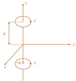
The given configuration is

I =
Range is
Calculation:
The figure for the loop structures carrying current can be drawn as below:
The equation for H because of small current element 'Idl' will be
The
The differential expression for magnetic field intensity will be
The vector starting from current loop to the concerned point at a height 'h' will be
The equation for H because of small current element 'Idl' will be
The differential expression for magnetic field intensity will be
Because of symmetry, the magnetic field is there only in the direction of
Integrating over an azimuthal angle
The total magnetic field due to upper ring will be
The total magnetic field due to lower ring will be
As the magnetic fields are linear, therefore, the magnetic field at point P will be the sum of both.
That is,
The above expression is the value of magnetic field on the positive side of the z axis.
The total magnetic field an any point on the z axis between the range
(b)
To plot:
The graph of
Explanation of Solution
Given:
The given configuration is

I =
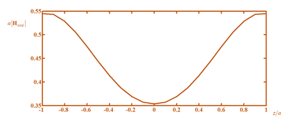
Calculation:
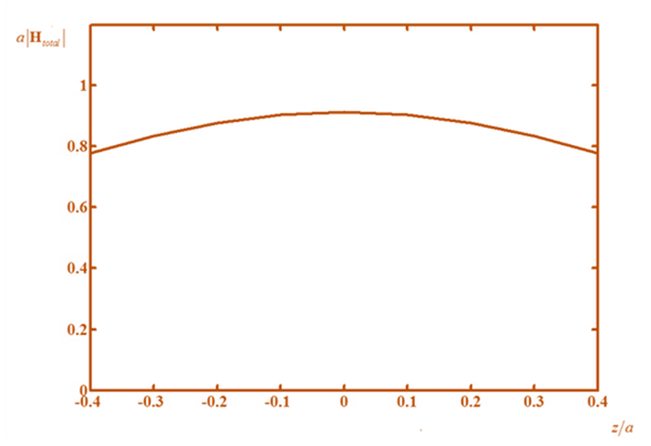
Substituting I = 1A and manipulating the equation for z/a, the modulus of total field will be
Put
Therefore, the plot will be
(c)
To plot:
The graph of
Explanation of Solution
Given:
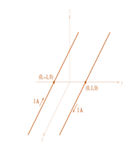
The given configuration is
I =
Calculation:
Substituting I = 1A and manipulating the equation for z / a, the modulus of total field will be
Put
Therefore, the plot will look li
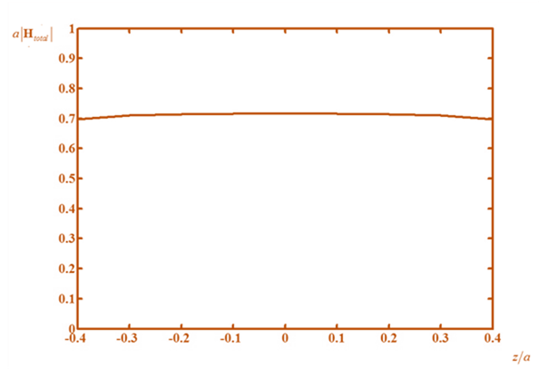
The most uniform field is obtained when
(d)
To plot:
The graph of
Answer to Problem 7.4P
The most uniform field is obtained when
Explanation of Solution
Given:
The given configuration is

I =
Calculation:
Substituting I = 1A and manipulating the equation for z/a, the modulus of total field will be
Put
Therefore, the plot will look like
Want to see more full solutions like this?
Chapter 7 Solutions
Engineering Electromagnetics


- Matlab Homework (20ps) A BFSK signal is transmitted through a channel with AWGN. Generate similar BFSK received signal plots as shown on next page. (20 pts) BFSK for eb-1 and npower=0.01 with 500 samples BFSK for eb=1 and npower=0.1 with 500 samples 2.5 2.5 2 1.5 1 0.5 0 -0.5 -1 2 1.5 1 0.5 0 0.5 -1 -1.5 1.5 -1.5 -1 -0.5 0 0.5 1 1.5 2 2.5 -1.5 -1 -0.5 0 0.5 1 1.5 2 2.5arrow_forwardCan you show how this answer was found?arrow_forward1. You are to design a 9-volt battery operated baseband PAM communication system that must last great than 10 years without replacing the batteries. The application requires a BER of <10^-4 and a data rate of 200bps. The channel can be modeled as AWGN with a noise power spectral density of 10^-9 W/Hz and a channel loss of 10 dB. (a) Estimate the required capacity of the batteries. (The battery life (hours) is equal to the battery volts times of the battery capacity (Amps* hours) divided by the total load (Watts)) and (b) Can you easily find this battery? If not, what would you suggest be done?arrow_forward
- 3. You are on a design team tasked to design a system of remote sensors that use PAM. Here is what the team knows/assumptions: The remote sensor will use a single AA battery required to power the sensors. The system has a bandwidth of 2KHz and requires a data rate of 12 Kbps and a BER of less than 1*10^-4. The typical channel has maximum losses of 35 dB and a noise power spectral density is 10^-9 W/Hz. Your boss assigns you with the task of estimating how long the battery will last.arrow_forward2. The noise power (in watts) measured in a baseband PAM communication channel is 230*10^-6 Watts. The transmitter output power is 600 mW and has a data rate of 300 Kbps. The channel bandwidth is 100 KHz with losses that can be modeled as 0.5dB/meter. The application requires a BER ofarrow_forwardQ27arrow_forwardI need help with this problem and an step by step explanation of the solution from the image described below. (Introduction to Signals and Systems)arrow_forwardI need help with this problem and an step by step explanation of the solution from the image described below. (Introduction to Signals and Systems)arrow_forwardI need help with this problem and an step by step explanation of the solution from the image described below. (Introduction to Signals and Systems)arrow_forwardarrow_back_iosSEE MORE QUESTIONSarrow_forward_ios
 Introductory Circuit Analysis (13th Edition)Electrical EngineeringISBN:9780133923605Author:Robert L. BoylestadPublisher:PEARSON
 Delmar's Standard Textbook Of ElectricityElectrical EngineeringISBN:9781337900348Author:Stephen L. HermanPublisher:Cengage Learning
 Programmable Logic ControllersElectrical EngineeringISBN:9780073373843Author:Frank D. PetruzellaPublisher:McGraw-Hill Education
 Fundamentals of Electric CircuitsElectrical EngineeringISBN:9780078028229Author:Charles K Alexander, Matthew SadikuPublisher:McGraw-Hill Education
 Electric Circuits. (11th Edition)Electrical EngineeringISBN:9780134746968Author:James W. Nilsson, Susan RiedelPublisher:PEARSON
 Engineering ElectromagneticsElectrical EngineeringISBN:9780078028151Author:Hayt, William H. (william Hart), Jr, BUCK, John A.Publisher:Mcgraw-hill Education,