
Principles of Foundation Engineering (MindTap Course List)
8th Edition
ISBN: 9781305081550
Author: Braja M. Das
Publisher: Cengage Learning
expand_more
expand_more
format_list_bulleted
Concept explainers
Videos
Textbook Question
thumb_up100%
Chapter 7, Problem 7.2P
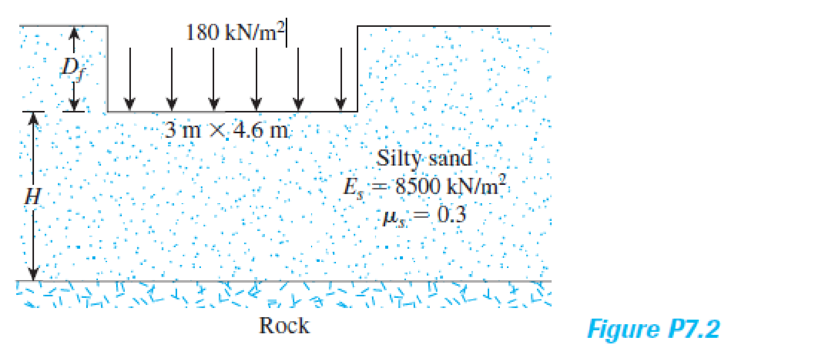
A planned flexible load area (see Figure P7.2) is to be 3 m × 4.6 m and carries a uniformly distributed load of 180 kN/m2. Estimate the elastic settlement below the center of the loaded area. Assume that Df = 2 m and H = ∞. Use Eq. (7.4).
Expert Solution & Answer

Trending nowThis is a popular solution!

Students have asked these similar questions
In a simulation experiment on a single lane road, one vehicle is travelling at 18 m/s.After 1.5seconds, the vehicle suddenly accelerates at a rate of 1.5 m/s2 for the next2 seconds and remains0 acceleration then after. Simulate the behavior of subsequent vehicle with an initial speedof16 m/s using GM car following model for the first 3 seconds if the initial distanceheadwayis 20 m. Tabulate the results. Assume headway exponent 1.2, speed exponent1.5, sensitivitycoefficient 0.8, reaction time 0.6 seconds, and update interval of0.3 seconds.
FORWARD FROM POINT B TO POINT A GIVEN THE FOLLOWING:
POINT BN=13,163,463.03'E=3,072,129.30'
DIRECTION FROM B TO A (NAZ)=276.07529°
DISTANCE FROM B TO A = 10.00'
It proposed to provide pile foundation for a heavy column; the pile group consisting of 4 piles.
placed at 2.0 m centre to centre, forming a square pattern. The under-ground soil is clay, having
cu at surface as 60 kN/m², and at depth 10 m, as 100 kN/m². Compute the allowable column
load on the pile cap with factor of safety of 3.0, if the piles are circular having diameters 0.5 m
each and length as 10 m.
Chapter 7 Solutions
Principles of Foundation Engineering (MindTap Course List)
Ch. 7 - Prob. 7.1PCh. 7 - A planned flexible load area (see Figure P7.2) is...Ch. 7 - Prob. 7.3PCh. 7 - Prob. 7.4PCh. 7 - Prob. 7.5PCh. 7 - Prob. 7.6PCh. 7 - Prob. 7.7PCh. 7 - Prob. 7.8PCh. 7 - Solve Problem 7.8 using Eq. (7.29). Ignore the...Ch. 7 - A continuous foundation on a deposit of sand layer...
Knowledge Booster


Learn more about
Need a deep-dive on the concept behind this application? Look no further. Learn more about this topic, civil-engineering and related others by exploring similar questions and additional content below.Similar questions
- At a particular section on a highway the following headways are observed: 0.04, 1.37,1.98,5.09, 3.00, 2.32, 2.54, 1.37, 0.94, 1.79, 1.10, 6.24, 4.82, 2.77, 4.82, 6.44. Fit an exponentialdistribution and compare the observed and estimated mean. Check the fit at the 5% level ofsignificance.arrow_forwardH.W: 1. Find the center of mass and the moment of inertia and radius of gyration about the y-axis of thin rectangular plate cut from the first quadrant by the lines x = 6 and y = 1 if (x, y) = x+y+1 2. Find the moment of inertia and radius of gyration about the coordinate axes of a thin rectangular plate of constant density & bounded by the lines x = 3 and y = 3 in the first quadrant.arrow_forwardPlease solve manually and follow all rules for flow net construction. Provide a scale such that the flow net produced can be copied.arrow_forward
- Please solve manually, and give any tips on how I can manually recreate the flow net you provide. Thanks.arrow_forwardA group of nine piles. 12m long and 350 mm in diameter, is to be arrenged in a square form in clay soil with an average unconfined compressive strength of 60 KN/m^2. Work out center to center spacing of the piles for a group effeciency factor of 1, Neglect bearing at the tip of the piles.arrow_forwardSOLVE BY NEWTON - RAPHSON METHOD: The equation x³-3x-4=0 is of the form f(x) = 0 where f(1) 0 so there is a solution to the equation between 1 and 3. We shall take this to be 2, by bisection. Find a better approximation to the root.arrow_forward
- Kindly help to provide answers, elaborate with examples and provide useful links for learning purposes. this is regarding building diagnosis.arrow_forwardpounds of steel need to be purchased for the roof plan a table with various steel types and the quantity needed The colums are 18 feet high and weigh 76 ponds per foot include a structural steel material list for the roof framing planarrow_forwardHomework: Determine the proportions of the separate aggregates that will give a gradation within the SCRB wearing coarse specified limits for the aggregates and mix composition for highway pavement asphaltic concrete. The table below shows the results of sieve analysis of samples from the materials available. برو Percent by Weight Passing Sieve Designation Retained on Sieve Designation Coarse Aggregate Fine Aggregate Mineral Filler 3/4 in. (19 mm) 1/2 in. 5 ½ in. (12.5 mm) 3/8 in. 35 ¾ in. (9.5 mm) No. 4 38 No. 4 (4.75 mm) No. 10 17 No. 10 (2 mm) No. 40 5 No. 40 (0.425 mm) No. 80 No. 80 (0.180 mm) No. 200 No. 200 (0.075 mm) Total 18 1118 30 35 5 26 35 60 100 100 100arrow_forward
- For the driven pile shown in figure, estimate the allowable capacity by: (a) Tomlinson a-method, (b)Vijayvergia and Focht A-method. Which one of the two methods are more conservative? Qall =? W.T 18.21 kN/m² 930 L=18m Square pile 27.5cm x 27.5cmarrow_forwardWhat is the vertical deflection at joint C of the truss shown? 75 kN 9 m 7 (3000 mm²) (3000 mm²) (2000 mm²) (3000 mm²) (2000 mm²) 100 kN (3000 mm²) H (3000 mm²) (2000 mm²) (2000 mm²) (3000 mm²)B(3000 mm²) C(3000 mm²)D(3000 mm2)5 a. 9.3 mm↓ b. 9.6 mm↓ c. 8.0 mm ↓ d. 9.1 mm↓ 4 at 6 m = 24 m E = 200 GPa Earrow_forwardINVERSE FROM POINT A TOWARDS POINT B GIVEN THE FOLLOWINGCOORDINATE VALUES: POINT AN=13,163,953.37'E=3,072,227.10' POINT BN=13,163,463.03'E=3,072,129.30' FIND THE FOLLOWING:DISTANCE FROM A TO BNORTH AZIMUTH (NAZ) FROM A TOWARDS BBEARING OF THE LINE FROM A TOWARDS Barrow_forward
arrow_back_ios
SEE MORE QUESTIONS
arrow_forward_ios
Recommended textbooks for you
 Principles of Foundation Engineering (MindTap Cou...Civil EngineeringISBN:9781305081550Author:Braja M. DasPublisher:Cengage Learning
 Principles of Geotechnical Engineering (MindTap C...Civil EngineeringISBN:9781305970939Author:Braja M. Das, Khaled SobhanPublisher:Cengage Learning
 Principles of Foundation Engineering (MindTap Cou...Civil EngineeringISBN:9781337705028Author:Braja M. Das, Nagaratnam SivakuganPublisher:Cengage Learning
 Fundamentals of Geotechnical Engineering (MindTap...Civil EngineeringISBN:9781305635180Author:Braja M. Das, Nagaratnam SivakuganPublisher:Cengage Learning
Principles of Foundation Engineering (MindTap Cou...
Civil Engineering
ISBN:9781305081550
Author:Braja M. Das
Publisher:Cengage Learning
Principles of Geotechnical Engineering (MindTap C...
Civil Engineering
ISBN:9781305970939
Author:Braja M. Das, Khaled Sobhan
Publisher:Cengage Learning
Principles of Foundation Engineering (MindTap Cou...
Civil Engineering
ISBN:9781337705028
Author:Braja M. Das, Nagaratnam Sivakugan
Publisher:Cengage Learning
Fundamentals of Geotechnical Engineering (MindTap...
Civil Engineering
ISBN:9781305635180
Author:Braja M. Das, Nagaratnam Sivakugan
Publisher:Cengage Learning
Stress Distribution in Soils GATE 2019 Civil | Boussinesq, Westergaard Theory; Author: Gradeup- GATE, ESE, PSUs Exam Preparation;https://www.youtube.com/watch?v=6e7yIx2VxI0;License: Standard YouTube License, CC-BY