
Concept explainers
Videos
For the beam shown, draw the shear and bending-moment diagrams, and determine the magnitude and location of the maximum absolute value of the bending moment, knowing that (a) M = 0, (b) M = 24 kip-ft.
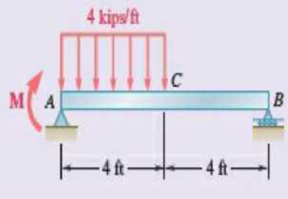
Fig. P7.161
(a)
Plot the shear force and bending moment diagram for the beam.
Find the magnitude and location of the maximum absolute value of the bending moment.
Answer to Problem 7.161RP
The location and magnitude of the maximum absolute bending moment is
Explanation of Solution
Given information:
The moment applied at A is
Calculation:
Show the free-body diagram of the entire beam as in Figure 1.
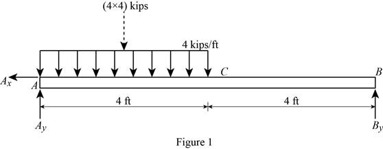
Find the vertical reaction at point B by taking moment about point A.
Find the vertical reaction at point A by reoslving the vertical component of forces.
Resolve the horizontal component of forces.
Consider the section AC:
Consider a section at a distance x from left end A.
Show the free-body diagram of the section as in Figure 2.
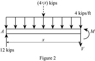
Resolve the vertical component of forces.
Take moment about the section.
At
Substitute 0 for x in Equation (1).
Substitute 0 for x in Equation (2).
At
Substitute 4 ft for x in Equation (1).
Substitute 4 ft for x in Equation (2).
Consider the section CB:
Show the free-body diagram of the section as in Figure 3.
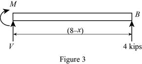
Resolve the vertical component of forces.
Take moment about the section.
At
Substitute 4 ft for x in Equation (3).
At
Substitute 8 ft for x in Equation (3).
Tabulate the shear force values as in Table 1.
| Location, x ft | Shear force, kips |
| 0 | 12 |
| 4 | –4 |
| 8 | –4 |
Plot the shear force diagram as in Figure 4.
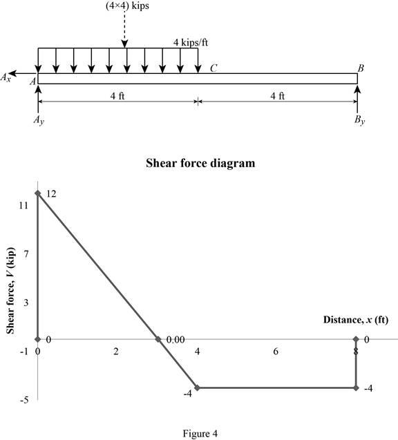
The maximum bending moment occurs where the shear force changes sign.
Refer to the Figure 4, the shear force changes in the section AC.
Substitute 0 for V in Equation (1).
Substitute 3 ft for x in Equaiton (2).
Tabulate the bending moment values as in Table 2.
| Location, x ft | Bending moment, kips-ft |
| 0 | 0 |
| 3 | 18 |
| 4 | 16 |
| 8 | 0 |
Plot the bending moment values as in Figure 5.
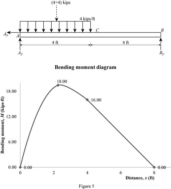
Therefore, the location and magnitude of the maximum absolute bending moment is
(b)
Plot the shear force and bending moment diagram for the beam.
Find the magnitude and location of the maximum absolute value of the bending moment.
Answer to Problem 7.161RP
The location and magnitude of the maximum absolute bending moment is
Explanation of Solution
Given information:
The moment applied at A is
Calculation:
Show the free-body diagram of the entire beam as in Figure 6.
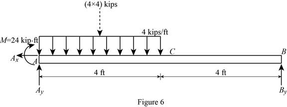
Find the vertical reaction at point B by taking moment about point A.
Find the vertical reaction at point A by reoslving the vertical component of forces.
Resolve the horizontal component of forces.
Consider the section AC:
Consider a section at a distance x from left end A.
Show the free-body diagram of the section as in Figure 7.
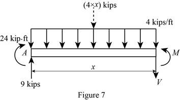
Resolve the vertical component of forces.
Take moment about the section.
At
Substitute 0 for x in Equation (4).
Substitute 0 for x in Equation (5).
At
Substitute 4 ft for x in Equation (4).
Substitute 4 ft for x in Equation (5).
Consider the section CB:
Show the free-body diagram of the section as in Figure 8.
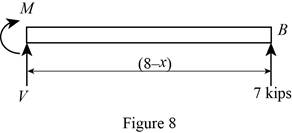
Resolve the vertical component of forces.
Take moment about the section.
At
Substitute 4 ft for x in Equation (6).
At
Substitute 8 ft for x in Equation (6).
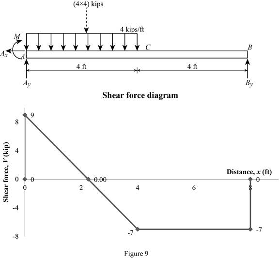
Tabulate the shear force values as in Table 3.
| Location, x ft | Shear force, kips |
| 0 | 9 |
| 4 | –7 |
| 8 | –7 |
Plot the shear force diagram as in Figure 9.
The maximum bending moment occurs where the shear force changes sign.
Refer to the Figure 4, the shear force changes in the section AC.
Substitute 0 for V in Equation (4).
Substitute 2.25 ft for x in Equaiton (5).
Tabulate the bending moment values as in Table 4.
| Location, x ft | Bending moment, kips-ft |
| 0 | 0 |
| 2.25 | 34.125 |
| 4 | 28 |
| 8 | 0 |
Plot the bending moment values as in Figure 10.
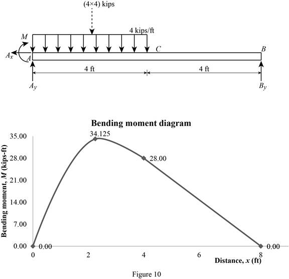
Therefore, the location and magnitude of the maximum absolute bending moment is
Want to see more full solutions like this?
Chapter 7 Solutions
VECTOR MECHANICS FOR ENGINEERS: STATICS


- Research and select any different values for the Ratio of connecting rod length to crank radius from various engine models, then analyze how these changes affect instantaneous velocity and acceleration, presenting your findings visually using graphs.arrow_forwardPb 9) 4.44 bas gnibus& WX 002 grillimatul fred bail (e) For the simply supported I-beam, a load of 1000 lb in center. Find the maximum transverse shear stress. Compare your answer with the approximation obtained by dividing the shear load by the area of the web only with the web considered to extend for the full 8-in depth. - 3½ in. 12 bas in 0% to tolerabib tormi no grived in. 8 in. 38 in. 12 ½ in.arrow_forwardPb 12) 4.61 Draw the Mohr circle for the stresses experienced by the surface of an internally pressurized steel tube that is subject to the tangential and axial stresses in the outer surface of 45 ksi and 30 ksi, respectively, and a torsional stress of 18 ksi. yx 18 45 30arrow_forward
- Pb 8) 4.39 For the C-clamp shown, what force F can be exerted by the screw if the maximum tensile stress in the clamp is to be limited to 30 ksi? F 2 in. სის 3436 16 13 blos 0101 alos12 nodus 121A (s 3 in. in. 16 in. 16 web leonas OFF elson yollA (d 016 (& d of bolow-bloo ai 15912 020112LA sue) vilisub 22 bal.90 Swman a bris ctxibasqqA) laste is tools?arrow_forwardQuiz/An eccentrically loaded bracket is welded to the support as shown in Figure below. The load is static. The weld size for weld w1 is h1 = 6mm, for w2 h2 = 5mm, and for w3 is h3 =5.5 mm. Determine the safety factor (S.f) for the welds. F=22 kN. Use an AWS Electrode type (E90xx). 140 S Find the centroid I want university professor solutions O REDMI NOTE 8 PRO CAI QUAD CAMERA 101.15 Farrow_forwardPb 6) 4.31 do = 25 mm 4.31 What bending moment is required to produce a maximum normal stress of 400 MPa: (a) In a straight round rod of 40-mm diameter? (b) In a straight square rod, 40 mm on a side (with bending about the X axis as shown for a rectangular section in Appendix B-2)?arrow_forward
- Pb 13) 4.73 Find the maximum value of stress at the hole and semicircular notch. 45000 N 50 mm 100 mm 15 mm 25 mm 45000 Narrow_forwardPb 11) 4.53 Consider the 1-in solid round shaft supported by self-aligning bearings at A and B. Attached to the shaft are two chain sprockets that are loaded as shown. Treat this as a static loading problem and identify the specific shat location subjected to the most severe state of stress and make a Mohr circle representation of this stress state. 1-in.-dia. shaft 500 lb 2 in. 1000 lb 3 in. 3 in.arrow_forwardPb 5) 4.19 Estimate the torque required to produce a maximum shear stress of 570 MPa in a hollow shaft having an inner diameter of 20 mm and an outer diameter of 25 mm. d; = 20 mm T d = 25 mm Tmax = 570 MPaarrow_forward
- Quiz/An eccentrically loaded bracket is welded to the support as shown in Figure below. The load is static. The weld size for weld w1 is h1 = 6mm, for w2 h2 = 5mm, and for w3 is h3 =5.5 mm. Determine the safety factor (S.f) for the welds. F=22 kN. Use an AWS Electrode type (E90xx). I want university professor solutions O REDMI NOTE 8 PRO CAI QUAD CAMERA 140 S 101.15 Farrow_forwardResearch and select different values for the R ratio from various engine models, then analyze how these changes affect instantaneous velocity and acceleration, presenting your findings visually using graphsarrow_forwardMeh Battery operated train Coll CD Af Pair 160,000kg 0.0005 0.15 5m² 1.2kg/m³ 19 7et nong 0.98 0.9 0.88 Tesla Prated Tesla Trated Ywheel ng Jaxle. 270kW 440NM 0.45m 20 2 8.5kgm² Consider a drive cycle of a 500km trip with 3 stops in the middle. Other than the acceleration and deceleration associated with the three stops, the tran maintains. constant cruise speed velocity of 324 km/hr. The tran will fast charge at each stop for 15 min at a rate Peharge = 350 kW (ผม τ (MN 15MIN Stop w charging (350kW GMIJ restored during 15 minutes of fast charging at Calculate the battery energy Pcharge = 350kW Calculate the net energy gain per stop t 64 Determice the total battery energy required Ebat to complete the 500km trip with 3 stops. etcarrow_forward
 Elements Of ElectromagneticsMechanical EngineeringISBN:9780190698614Author:Sadiku, Matthew N. O.Publisher:Oxford University Press
 Mechanics of Materials (10th Edition)Mechanical EngineeringISBN:9780134319650Author:Russell C. HibbelerPublisher:PEARSON
 Thermodynamics: An Engineering ApproachMechanical EngineeringISBN:9781259822674Author:Yunus A. Cengel Dr., Michael A. BolesPublisher:McGraw-Hill Education
 Control Systems EngineeringMechanical EngineeringISBN:9781118170519Author:Norman S. NisePublisher:WILEY
 Mechanics of Materials (MindTap Course List)Mechanical EngineeringISBN:9781337093347Author:Barry J. Goodno, James M. GerePublisher:Cengage Learning
 Engineering Mechanics: StaticsMechanical EngineeringISBN:9781118807330Author:James L. Meriam, L. G. Kraige, J. N. BoltonPublisher:WILEY