
Concept explainers
7.35 and 7.36 For the beam and loading shown, (a) draw the shear and bending-moment diagrams, (b) determine the maximum absolute values of the shear and bending moment.
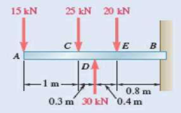
Fig. P7.35
(a)
The shear and bending-moment diagrams.
Answer to Problem 7.35P
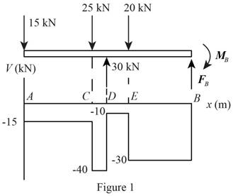
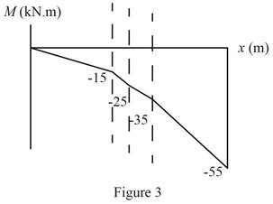
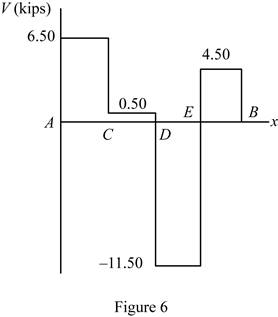
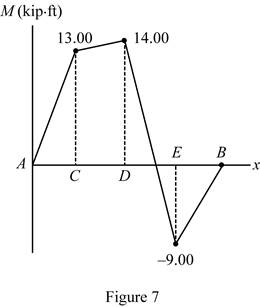
The shear diagram is drawn in figure 6 and bending momentum is drawn in figure 7.
Explanation of Solution
Refer Figure 1.
Refer Figure 2.
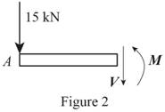
Write an expression to calculate the net counter clockwise moment at point C along AC.
Here,
Write an expression to calculate the net vertical force along AC.
Here,
Refer Figure 3.
Write an expression to calculate the net counter clockwise moment at point D along CD.
Here,
Write an expression to calculate the net vertical force along CD.
Refer Figure 4.
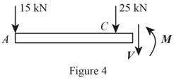
Write an expression to calculate the net counter clockwise moment at point E along DE.
Here,
Write an expression to calculate the net vertical force along EB.
Refer Figure 5.
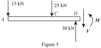
Write an expression to calculate the net counter clockwise moment at point B along EB.
Here,
Write an expression to calculate the net vertical force along EB.
Conclusion:
Refer Figure 2 and equation (II). Calculate the net vertical force.
Here,
Rearrange the equation to calculate
Refer Figure 2 and equation (I). Calculate the net counter clockwise moment at point C.
Here,
Rearrange the equation to calculate
Refer Figure 3 and equation (IV). Calculate the net vertical force.
Rearrange the equation to calculate
Refer Figure 3 and equation (III). Calculate the net counter clockwise moment at point D.
Rearrange the equation to calculate
Refer Figure 4 and equation (VI). Calculate the net vertical force.
Rearrange the equation to calculate
Refer Figure 4 and equation (V). Calculate the net counter clockwise moment at point E.
Rearrange the equation to calculate
Refer Figure 5 and equation (VIII). Calculate the net vertical force.
Rearrange the equation to calculate
Refer Figure 5 and equation (VII). Calculate the net counter clockwise moment at point E.
Rearrange the equation to calculate
Thus, draw the shear diagram.
Thus, draw the bending-moment.
(b)
The maximum absolute value of the shear and bending moment.
Answer to Problem 7.35P
The maximum absolute value of the shear force is
Explanation of Solution
Determine the maximum absolute shear from diagram 2. The maximum absolute value of bending moment is at maximum shear force.
Conclusion:
Refer figure 6. Determine the maximum absolute value of shear force.
Here,
Refer figure 7. Determine the maximum value of the bending moment at position B.
Here,
Thus, the maximum absolute value of the shear force is
Want to see more full solutions like this?
Chapter 7 Solutions
VECTOR MECHANICS FOR ENGINEERS: STATICS
- PROBLEMS 5.16, 5.17 Draw the shear and bending- moment diagrams for the beam and loading shown, and determine the maximum absolute value (a) of the shear, and (b) of the bending moment. 68 kN 30 kN/m D -1.2 m 1.2 m 1.2 m- Fig. P5.16 PROBLEM 5.21 For the beam and loading shown, bending stress on a transverse sectiarrow_forward7.33 and 7.34 For the beam and loading shown, (a) draw the shear and bending-moment diagrams, (b) determine the maximum absolute values of the shear and bending moment. kip kips CDE A 2 kips 3.6 ft 3 ft Fig. P7.33 3 ft 3.6 ftarrow_forwardFor the beam and loading shown, (a) draw the shear and bending-moment diagrams, (b) determine the maximum absolute values of the shear and bending moment.arrow_forward
- Using the method of Sec. 7.3, solve Prob. 7.41.(Reference to Problem 7.41):For the beam and loading shown, (a) draw the shear and bending-moment diagrams, (b) determine the maximum absolute values of the shear and bending moment.arrow_forwardPROBLEM 7.40 80 kN NA OE For the beam and loading shown, (a) draw the shear and bending- moment diagrams, (b) detemine the maximum absolute values of the shear and bending moment. D' 3m 2 m 2 m Fig. P7.40arrow_forward7.74 For the beam shown, draw the shear and bending-moment dia- grams, and determine the maximum absolute value of the bending moment knowing that (a) P = 7 kips, (b) P = 10 kips. 2 kips/ft 3 kips B A 8 ft + 6 ft → 6 ft → Fig. P7.74arrow_forward
- Problem 5.14 please thanksarrow_forwardSolve Prob. 7.43 knowing that P= 3wa.(Reference to Problem 7.43):Assuming the upward reaction of the ground on beam AB to be uniformly distributed and knowing that P= wa, (a) draw the shear and bending-moment diagrams, (b) determine the maximum absolute values of the shear and bending moment.arrow_forward7.78 For beam AB, (a) draw the shear and bending-moment diagrams, (b) determine the location and magnitude of the maximum absolute value of the bending moment. 1 kip/ft I kip A EQ 2 kips lo-12 ft 8 ft '4 ft' 8 ft Fig. P7.78arrow_forward
- 7.C4 Determine the equations for the shear and bending moment curves for beams 1 and 2 shown assuming that wo = 15 kN/m and L = 3 m. Plot the shear and bending moment diagrams for each beam. TTX w = wy sin L w = wo В A L Beam 1 Beam 2 Fig. P7.C4arrow_forwardPROBLEMS 5.16, 5.17 Draw the shear and bending- moment diagrams for the beam and loading shown, and determine the maximum absolute value (a) of the shear, and (b) of the bending moment. 65 kN 30 kN/m D A -1.2 m→-1.2 m -1.2 m→arrow_forwardPlease write out your equations and free body diagrams. Anything that is typed gets weird in the formatting and i cannot understand it. Thank youarrow_forward
 Elements Of ElectromagneticsMechanical EngineeringISBN:9780190698614Author:Sadiku, Matthew N. O.Publisher:Oxford University Press
 Mechanics of Materials (10th Edition)Mechanical EngineeringISBN:9780134319650Author:Russell C. HibbelerPublisher:PEARSON
 Thermodynamics: An Engineering ApproachMechanical EngineeringISBN:9781259822674Author:Yunus A. Cengel Dr., Michael A. BolesPublisher:McGraw-Hill Education
 Control Systems EngineeringMechanical EngineeringISBN:9781118170519Author:Norman S. NisePublisher:WILEY
 Mechanics of Materials (MindTap Course List)Mechanical EngineeringISBN:9781337093347Author:Barry J. Goodno, James M. GerePublisher:Cengage Learning
 Engineering Mechanics: StaticsMechanical EngineeringISBN:9781118807330Author:James L. Meriam, L. G. Kraige, J. N. BoltonPublisher:WILEY


