
Concept explainers
Find the vertical deflection at joint E of the frame using virtual work method.
Answer to Problem 50P
The vertical deflection at joint E of the frame is
Explanation of Solution
Given information:
The frame is given in the Figure.
The value of E is 200 GPa and I is
Apply the sign conventions for calculating reactions, forces and moments using the three equations of equilibrium as shown below.
- For summation of forces along x-direction is equal to zero
- For summation of forces along y-direction is equal to zero
- For summation of moment about a point is equal to zero
Calculation:
Consider the real system.
Draw a diagram showing all the given real loads acting on it.
Let the bending moment due to real load be
Sketch the real system of the frame as shown in Figure 1.
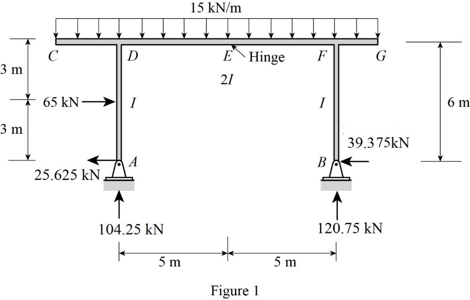
Find the reactions at the supports A and B:
Summation of moments about A is equal to 0.
Summation of forces along y-direction is equal to 0.
Consider ACDE, summation of moments about E is equal to 0.
Summation of forces along x-direction is equal to 0.
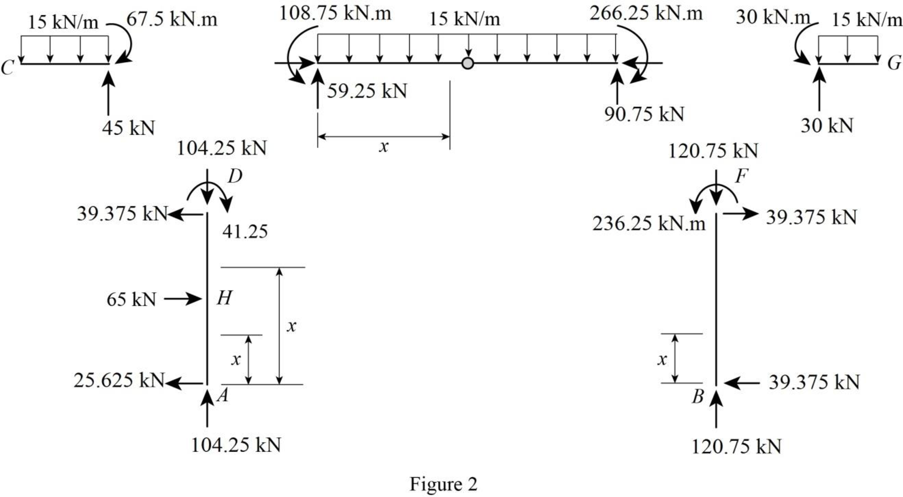
Sketch the member end forces of the real system as shown in Figure 2.
Consider the virtual system.
Draw a diagram of frame without the given real loads. For vertical deflection apply unit load at the joint in the vertical direction.
Let the bending moment due to virtual load be
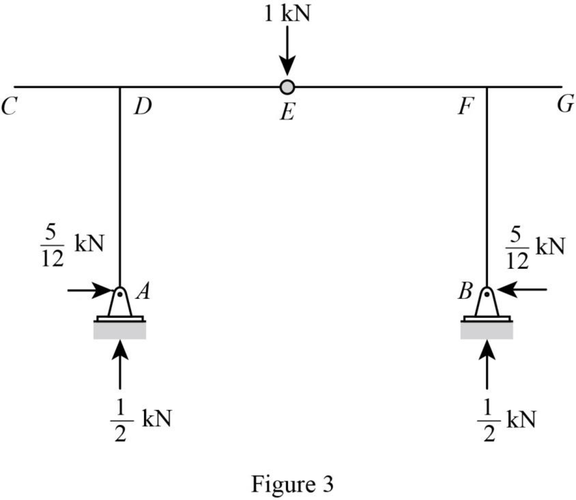
Sketch the virtual system of the frame with unit load at joint E as shown in Figure 3.
Find the reactions at the supports A and B:
Summation of moments about A is equal to 0.
Summation of forces along y-direction is equal to 0.
Consider ACDE, summation of moments about E is equal to 0.
Summation of forces along x-direction is equal to 0.
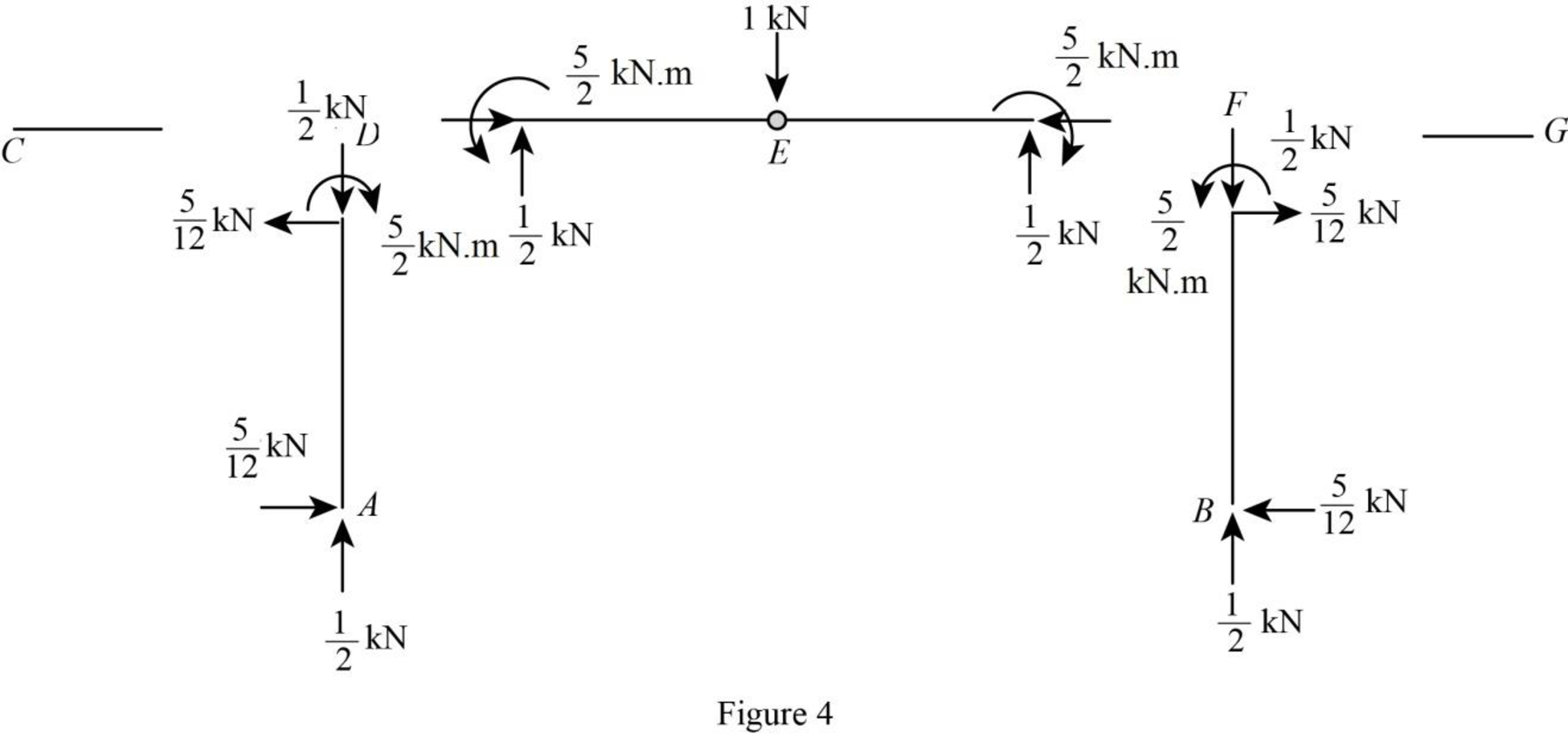
Sketch the member end forces of the virtual system as shown in Figure 4.
Find the equations for M and
| Segment | x-coordinate |
M |
| |
| Origin | Limits (m) | |||
| AH | A | |||
| HD | A | |||
| BF | B | |||
| DE | D | |||
| FE | F | |||
Find the vertical deflection at E using the virtual work expression:
Moment of inertia of span AH is I, moment of inertia of span HD is I, moment of inertia of span BF is I, moment of inertia of span DE is 2I, and moment of inertia of span FE is 2I.
Rearrange Equation (1) for the limits
Substitute
Substitute 200 GPa for E and
Therefore, the vertical deflection at E is
Want to see more full solutions like this?
Chapter 7 Solutions
Structural Analysis (MindTap Course List)


- YOU HAVE A UNIFORM SUBGRADE ELEVATION FOR YOUR BUILDING FOUNDATION THAT HASBEEN VERIFIED. YOUR SLAB IS DESIGNED TO BE 12 INCHES THICK.USING THE GIVENDIMENSIONS AROUND THE PROPOSED BUILDING FOUNDATION, CALCULATE THE CUBIC FEETAND THE CUBIC YARDS OF CONCRETE NEEDED FOR THE FOUNDATION **Sketch Attached**arrow_forwardWHAT ARE THE COORDINATES (N,E) AT POINT A AND POINT B IN THE SKETCH (ATTACHED)arrow_forwardCan you please do with hand calcs and answer the following: a Determine the global stiffness matrix (K) of the beam including indicating correct degrees-of freedom (dof) b i) Calculate vectors D and Q ii) Show partition and solve KD=Q for D iii) Calculate all reactions c BMD & max BM, deflected shape d i) Solve the problem using Strand7 (model) ii) Display the deflected shape and BMD e Comparisons of reactions + Max BM including commentsarrow_forward
- 5-1. Determine the force in each member of the truss, and state if the members are in tension or compression.arrow_forwardI have the correct answer provided, just lookng for a more detailed breadown of how the answer was obtained thanks.arrow_forwardQ1. Statically indeterminate beam analysis. a) Calculate the BMs (bending moments) at all the joints of the beam shown in Fig.1 using the moment distribution method. The beam is subjected to an UDL of w kN/m. L1= 0.4L. Assume the support at C is pinned, and A and B are roller supports. E = 200 GPa, I=250x106 mm². Use the values of w = 50 kN/m and L = 6 b) Draw the shear force and bending diagrams for the entire beam. c) Calculate the BMs at all the joints of the same beam shown in Fig.1 using the slope deflection method. d) Compare the values of BMs obtained using the two methods a) and c) and comment. w kN/m £1m Lm m Fig 1. Beam for Q1arrow_forward
- I have the answer provided for the question, just looking for a more detailed breadown of how it was obtained thanks.arrow_forwardQ5.--Finite-element-modelling. a) → Draw-a-2D-element-and-show-the dots (degrees of freedom). Draw-all-the-2D-elements. used-in-Strand 7..Explain the differences between-these-elements-in-terms-of-the-no..of. nodes-and-interpolation/shape-functions used. b)→A-8-m-x-8-m-plate (in-the-xx-plane)-with-8-mm-thickness, is fixed-at-all-the-edges.and.is. loaded-by-a-pressure-loading-of-4 kN/m2.-in-the-downward-(-2)-direction.-The-plate.is. made-of-steel-(E=-200 GPa, density-7850-kg/m3). Explain-the-steps-involved-in-setting. up-a-Strand 7-model-for-this-problem. Your-explanation-should-include-how-the-given. input-data-for-this-problem-will-be-used-in-Strand 7-modelling. Explain how you would. determine the maximum-deflection-from-the-Strand 7-output.-1 11arrow_forwardI need Help some hw for AutoCAD please use measure front top and side viewarrow_forward
- Calculate the discharge of the system shown below. Neglecting minor losessarrow_forwardQ3. Statically determinate or indeterminate beam analysis by the stiffness method a) Determine the global stiffness matrix of the beam shown in Fig. 3. Assume supports at 1 and 3 are rollers and the support at 2 is a pinned support. Indicate the degrees- of freedom in all the stiffness matrices. El is constant. Use the values of w = 50 kN/m and L1 = 2.0 m Note, L2-3L1. b) Determine the rotations at all the nodes of the beam and reactions at the supports. Show all calculations. c) Draw the BMD of the beam on the compression side showing the salient values. What are the maximum bending moments of the beam? Draw the deflected shape of the beam. d) Solve the problem using the Strand7. Assume any suitable value of El (state the value you have used for El). Show the model with all the nodes, element numbers and boundary conditions. Display the deflected shape and BMD. e) Show a table comparing the stiffness method (manual calculations) of the all the reactions and the maximum bending moment…arrow_forwardUsing AutoCAD. I need help please to exact measurearrow_forward
