
MECHANICS OF MATERIALS (LOOSE)-W/ACCESS
10th Edition
ISBN: 9780134583228
Author: HIBBELER
Publisher: PEARSON
expand_more
expand_more
format_list_bulleted
Videos
Textbook Question
Chapter 6.4, Problem 6.91P
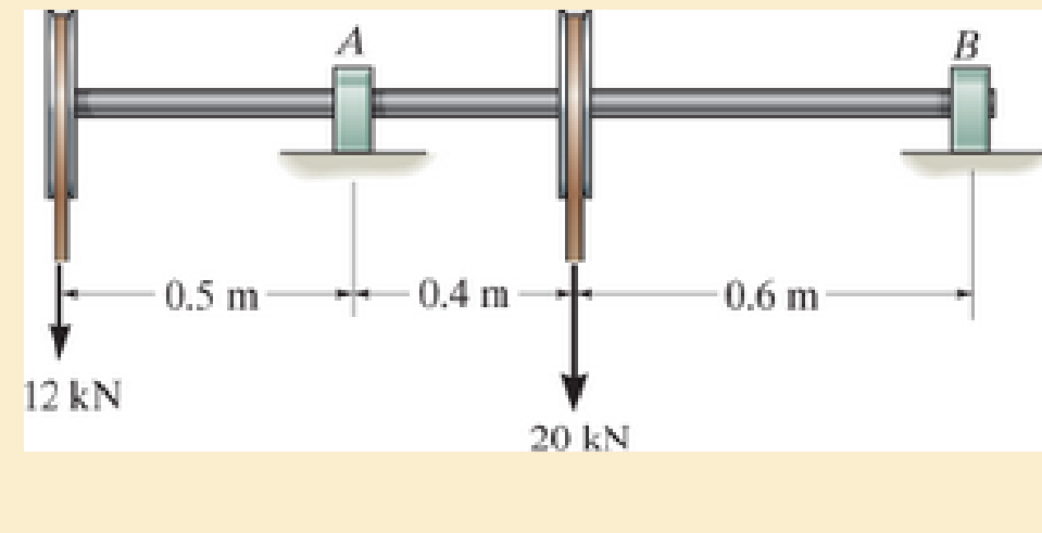
Determine the absolute maximum bending stress in the 80-mm-diameter shaft which is subjected to the concentrated forces. There is a journal bearing at A and a thrust bearing at B.
Expert Solution & Answer
Want to see the full answer?
Check out a sample textbook solution
Students have asked these similar questions
Continuity equation
A
y
x
dx
D
T
معادلة الاستمرارية
Ly
X
Q/Prove that
ди
хе
+ ♥+ ㅇ?
he
me
ze
ོ༞“༠ ?
Q
Derive (continuity equation)?
I want to derive clear mathematics.
motor supplies 200 kW at 6 Hz to flange A of the shaft shown in Figure. Gear B transfers 125 W of power to operating machinery in the factory, and the remaining power in the shaft is mansferred by gear D. Shafts (1) and (2) are solid aluminum (G = 28 GPa) shafts that have the same diameter and an allowable shear stress of t= 40 MPa. Shaft (3) is a solid steel (G = 80 GPa) shaft with an allowable shear stress of t = 55 MPa. Determine:
a) the minimum permissible diameter for aluminum shafts (1) and (2)
b) the minimum permissible diameter for steel shaft (3).
c) the rotation angle of gear D with respect to flange A if the shafts have the minimum permissible diameters as determined in (a) and (b).
Chapter 6 Solutions
MECHANICS OF MATERIALS (LOOSE)-W/ACCESS
Ch. 6.2 - In each case, the beam is subjected to the...Ch. 6.2 - and then draw the shear and moment diagrams for...Ch. 6.2 - In each case, express the shear and moment...Ch. 6.2 - In each case, express the shear and moment...Ch. 6.2 - In each case, express the shear and moment...Ch. 6.2 - In each case, draw the shear and moment diagrams...Ch. 6.2 - In each case, draw the shear and moment diagrams...Ch. 6.2 - In each case, draw the shear and moment diagrams...Ch. 6.2 - In each case, draw the shear and moment diagrams...Ch. 6.2 - Draw the shear and moment diagrams for the shaft...
Ch. 6.2 - Draw the shear and moment diagrams for the beam,...Ch. 6.2 - Draw the shear and moment diagrams for the beam,...Ch. 6.2 - Express the shear and moment in terms of x for 0 ...Ch. 6.2 - Express the internal shear and moment in the...Ch. 6.2 - Draw the shear and moment diagrams for the shaft....Ch. 6.2 - Express the internal shear and moment in terms of...Ch. 6.2 - Draw the shear and moment diagrams for the beam,...Ch. 6.2 - If the force applied to the handle of the load...Ch. 6.2 - Draw the shear and moment diagrams for the shaft....Ch. 6.2 - The crane is used to support the engine, which has...Ch. 6.2 - Draw the shear and moment diagrams for the beam....Ch. 6.2 - Draw the shear and moment diagrams for the beam....Ch. 6.2 - Draw the shear and moment diagrams for the beam....Ch. 6.2 - Members ABC and BD of the counter chair are...Ch. 6.2 - A reinforced concrete pier is used to support the...Ch. 6.2 - Draw the shear and moment diagrams for the beam...Ch. 6.2 - The industrial robot is held in the stationary...Ch. 6.2 - Determine the placement distance a of the roller...Ch. 6.2 - Draw the shear and moment diagrams for the beam....Ch. 6.2 - Draw the shear and moment diagrams for the beam....Ch. 6.2 - Draw the shear and moment diagrams for the...Ch. 6.2 - The 150-lb man sits in the center of the boat,...Ch. 6.2 - Draw the shear and moment diagrams for the beam....Ch. 6.2 - The footing supports the load transmitted by the...Ch. 6.2 - Draw the shear and moment diagrams for the beam....Ch. 6.2 - Draw the shear and moment diagrams for the beam....Ch. 6.2 - Draw the shear and moment diagrams for the beam....Ch. 6.2 - Draw the shear and moment diagrams for the beam....Ch. 6.2 - Draw the shear and moment diagrams for the beam....Ch. 6.2 - The support at A allows the beam to slide freely...Ch. 6.2 - The smooth pin is supported by two leaves A and B...Ch. 6.2 - The shaft is supported by a smooth thrust bearing...Ch. 6.2 - Draw the shear and moment diagrams for the...Ch. 6.2 - Draw the shear and moment diagrams for the beam....Ch. 6.2 - Draw the shear and moment diagrams for the rod....Ch. 6.2 - Draw the shear and moment diagrams for the beam...Ch. 6.2 - The beam is used to support a uniform load along...Ch. 6.2 - Draw the shear and moment diagrams for the double...Ch. 6.2 - Draw the shear and moment diagrams for the simply...Ch. 6.2 - The compound beam is fixed at A, pin connected at...Ch. 6.2 - Draw the shear and moment diagrams for the...Ch. 6.2 - The compound beam is fixed at A, pin connected at...Ch. 6.2 - Draw the shear and moment diagrams for the beam....Ch. 6.2 - A short link at B is used to connect beams AB and...Ch. 6.2 - The truck is to be used to transport the concrete...Ch. 6.4 - Determine the moment of inertia of the cross...Ch. 6.4 - Determine the location of the centroid, y, and the...Ch. 6.4 - In each case, show how the bending stress acts on...Ch. 6.4 - Sketch the bending stress distribution over each...Ch. 6.4 - If the beam is subjected to a bending moment of M...Ch. 6.4 - If the beam is subjected to a bending moment of M...Ch. 6.4 - If the beam is subjected to a bending moment of M...Ch. 6.4 - If the beam is subjected to a bending moment of M...Ch. 6.4 - If the beam is subjected to a bending moment of M...Ch. 6.4 - An A-36 steel strip has an allowable bending...Ch. 6.4 - Determine the moment M that will produce a maximum...Ch. 6.4 - Determine the maximum tensile and compressive...Ch. 6.4 - The beam is constructed from four pieces of wood,...Ch. 6.4 - The beam is constructed from four pieces of wood,...Ch. 6.4 - The beam is made from three boards nailed together...Ch. 6.4 - The beam is made from three boards nailed together...Ch. 6.4 - If the built-up beam is subjected to an internal...Ch. 6.4 - If the built-up beam is subjected to an internal...Ch. 6.4 - The beam is subjected to a moment of M = 40 kN m....Ch. 6.4 - The steel shaft has a diameter of 2 in. It is...Ch. 6.4 - The beam is made of steel that has an allowable...Ch. 6.4 - A shaft is made of a polymer having an elliptical...Ch. 6.4 - Solve Prob. 6-65 if the moment M = 50 N m is...Ch. 6.4 - Prob. 6.67PCh. 6.4 - The shaft is supported by smooth journal bearings...Ch. 6.4 - The axle of the freight car is subjected to a...Ch. 6.4 - The strut on the utility pole supports the cable...Ch. 6.4 - The boat has a weight of 2300 lb and a center of...Ch. 6.4 - Determine the absolute maximum bending stress in...Ch. 6.4 - Determine the smallest allowable diameter of the...Ch. 6.4 - The pin is used to connect the three links...Ch. 6.4 - The shaft is supported by a thrust bearing at A...Ch. 6.4 - A timber beam has a cross section which is...Ch. 6.4 - If the beam is subjected to an internal moment of...Ch. 6.4 - If the allowable tensile and compressive stress...Ch. 6.4 - If the beam is subjected to an internal moment of...Ch. 6.4 - If the beam is subjected to a moment of M = 100 kN...Ch. 6.4 - If the beam is made of material having an...Ch. 6.4 - The shaft is supported by a smooth thrust bearing...Ch. 6.4 - The shaft is supported by a thrust bearing at A...Ch. 6.4 - If the intensity of the load w = 15 kN/m,...Ch. 6.4 - If the allowable bending stress is allow = 150...Ch. 6.4 - The beam is subjected to the triangular...Ch. 6.4 - The beam has a rectangular cross section with b =...Ch. 6.4 - Prob. 6.88PCh. 6.4 - If the compound beam in Prob. 642 has a square...Ch. 6.4 - If the beam in Prob. 628 has a rectangular cross...Ch. 6.4 - Determine the absolute maximum bending stress in...Ch. 6.4 - Determine, to the nearest millimeter, the smallest...Ch. 6.4 - Determine the absolute maximum bending stress in...Ch. 6.4 - Determine the absolute maximum bending stress in...Ch. 6.4 - Determine the smallest diameter of the shaft to...Ch. 6.4 - A log that is 2 ft in diameter is to be cut into a...Ch. 6.4 - A log that is 2 ft in diameter is to be cut into a...Ch. 6.4 - If the beam in Prob.63 has a rectangular cross...Ch. 6.4 - The simply supported truss is subjected to the...Ch. 6.4 - If d = 450 mm, determine the absolute maximum...Ch. 6.4 - If the allowable bending stress is allow = 6 MPa,...Ch. 6.4 - The beam has a rectangular cross section as shown....Ch. 6.4 - The beam has the rectangular cross section shown....Ch. 6.5 - Determine the bending stress at corners A and B....Ch. 6.5 - Determine the maximum bending stress in the beams...Ch. 6.5 - The member has a square cross section and is...Ch. 6.5 - The member has a square cross section and is...Ch. 6.5 - Consider the general case of a prismatic beam...Ch. 6.5 - Determine the bending stress at point A of the...Ch. 6.5 - Determine the bending stress at point A of the...Ch. 6.5 - The steel shaft is subjected to the two loads. If...Ch. 6.5 - The 65-mm-diameter steel shaft is subjected to the...Ch. 6.5 - For the section, lz = 31.7(10-5) m4, lY =...Ch. 6.5 - For the section, lz, = 31.7(10-5) m4, lY =...Ch. 6.5 - The box beam is subjected to a moment of M = 15...Ch. 6.5 - Determine the maximum magnitude of the bending...Ch. 6.5 - The shaft is subjected to the vertical and...Ch. 6.5 - For the section, Iy' = 31.7(10-6) m4, Iz' =...Ch. 6.5 - For the section, Iy' = 31.7(10-6) m4, Iz' =...Ch. 6.5 - If the applied distributed loading of w = 4 kN/m...Ch. 6.5 - Determine the maximum allowable intensity w of the...Ch. 6.9 - The composite beam is made of steel (A) bonded to...Ch. 6.9 - The composite beam is made of steel (A) bonded to...Ch. 6.9 - Segment A of the composite beam is made from...Ch. 6.9 - Segment A of the composite beam is made from...Ch. 6.9 - The white spruce beam is reinforced with A-992...Ch. 6.9 - The wooden section of the beam is reinforced with...Ch. 6.9 - The wooden section of the beam is reinforced with...Ch. 6.9 - The Douglas Fir beam is reinforced with A-992...Ch. 6.9 - The steel channel is used to reinforce the wood...Ch. 6.9 - A wood beam is reinforced with steel straps at its...Ch. 6.9 - A bimetallic strip is made from pieces of 2014-T6...Ch. 6.9 - Determine the maximum uniform distributed load w0...Ch. 6.9 - The composite beam is made of A-36 steel (A)...Ch. 6.9 - The composite beam is made of A-36 steel (A)...Ch. 6.9 - If the beam is subjected to a moment of M = 45 kN...Ch. 6.9 - The Douglas Fir beam is reinforced with A-36 steel...Ch. 6.9 - For the curved beam in Fig. 640a, show that when...Ch. 6.9 - The curved member is subjected to the moment of M...Ch. 6.9 - The curved member is made from material having an...Ch. 6.9 - The curved beam is subjected to a moment of M = 40...Ch. 6.9 - The curved beam is made from material having an...Ch. 6.9 - If P = 3 kN, determine the bending stress at...Ch. 6.9 - If the maximum bending stress at section a-a is...Ch. 6.9 - The elbow of the pipe has an outer radius of 0.75...Ch. 6.9 - If the bar is subjected to a couple as shown,...Ch. 6.9 - The curved bar used on a machine has a rectangular...Ch. 6.9 - The steel rod has a circular cross section. If it...Ch. 6.9 - If it is subjected to a moment of M = 5 kN m,...Ch. 6.9 - The member has a circular cross section. If the...Ch. 6.9 - The curved bar used on a machine has a rectangular...Ch. 6.9 - The bar is subjected to a moment of M = 100 N, m....Ch. 6.9 - The allowable bending stress for the bar is allow...Ch. 6.9 - The bar has a thickness of 1 in. and the allowable...Ch. 6.9 - The bar has a thickness of 1 in. and is subjected...Ch. 6.9 - The bar has a thickness of 0.5 in. and the...Ch. 6.9 - If the radius of each notch on the plate is r = 10...Ch. 6.9 - The stepped bar has a thickness of 10 mm....Ch. 6.9 - The bar has a thickness of 0.5 in. and is...Ch. 6.10 - Determine the shape factor for the wide-flange...Ch. 6.10 - The wide-flange member is made from an elastic...Ch. 6.10 - The rod has a circular cross section. If it is...Ch. 6.10 - The rod has a circular cross section. If it is...Ch. 6.10 - The beam is made of an elastic perfectly plastic...Ch. 6.10 - Determine the plastic moment Mp that can be...Ch. 6.10 - Determine the shape factor for the beam. Prob....Ch. 6.10 - The beam is made of elastic perfectly plastic...Ch. 6.10 - Determine the shape factor for the beam. Prob....Ch. 6.10 - The beam is made of an elastic perfectly plastic...Ch. 6.10 - Prob. 6.168PCh. 6.10 - Prob. 6.169PCh. 6.10 - Prob. 6.170PCh. 6.10 - The rod has a circular cross section. If it is...Ch. 6.10 - Determine the shape factor of the cross section....Ch. 6.10 - The beam is made of elastic perfectly plastic...Ch. 6.10 - Determine the shape factor for the member having...Ch. 6.10 - Determine the shape factor of the cross section....Ch. 6.10 - The box beam is made of an elastic perfectly...Ch. 6.10 - The beam is made of an elastic perfectly plastic...Ch. 6.10 - The plexiglass bar has a stress-strain curve that...Ch. 6.10 - The stress-strain diagram for a titanium alloy can...Ch. 6.10 - A beam is made from polypropylene plastic and has...Ch. 6.10 - The bar is made of an aluminum alloy having a...Ch. 6.10 - The beam is made of phenolic, a structural...Ch. 6 - Using appropriate measurements and data, explain...Ch. 6 - Determine the shape factor for the wide-flange...Ch. 6 - The compound beam consists of two segments that...Ch. 6 - The composite beam consists of a wood core and two...Ch. 6 - If it resists a moment of M = 125 N m, determine...Ch. 6 - Determine the maximum bending stress in the handle...Ch. 6 - The curved beam is subjected to a bending moment...Ch. 6 - Determine the shear and moment in the beam as...Ch. 6 - A wooden beam has a square cross section as shown...Ch. 6 - Draw the shear and moment diagrams for the shaft...Ch. 6 - The strut has a square cross section a by a and is...
Knowledge Booster


Learn more about
Need a deep-dive on the concept behind this application? Look no further. Learn more about this topic, mechanical-engineering and related others by exploring similar questions and additional content below.Similar questions
- First monthly exam Gas dynamics Third stage Q1/Water at 15° C flow through a 300 mm diameter riveted steel pipe, E-3 mm with a head loss of 6 m in 300 m length. Determine the flow rate in pipe. Use moody chart. Q2/ Assume a car's exhaust system can be approximated as 14 ft long and 0.125 ft-diameter cast-iron pipe ( = 0.00085 ft) with the equivalent of (6) regular 90° flanged elbows (KL = 0.3) and a muffler. The muffler acts as a resistor with a loss coefficient of KL= 8.5. Determine the pressure at the beginning of the exhaust system (pl) if the flowrate is 0.10 cfs, and the exhaust has the same properties as air.(p = 1.74 × 10⁻³ slug/ft³, u= 4.7 x 10⁻⁷ lb.s/ft²) Use moody chart (1) MIDAS Kel=0.3 Q3/Liquid ammonia at -20°C is flowing through a 30 m long section of a 5 mm diameter copper tube(e = 1.5 × 10⁻⁶ m) at a rate of 0.15 kg/s. Determine the pressure drop and the head losses. .μ= 2.36 × 10⁻⁴ kg/m.s)p = 665.1 kg/m³arrow_forward2/Y Y+1 2Cp Q1/ Show that Cda Az x P1 mactual Cdf Af R/T₁ 2pf(P1-P2-zxgxpf) Q2/ A simple jet carburetor has to supply 5 Kg of air per minute. The air is at a pressure of 1.013 bar and a temperature of 27 °C. Calculate the throat diameter of the choke for air flow velocity of 90 m/sec. Take velocity coefficient to be 0.8. Assume isentropic flow and the flow to be compressible. Quiz/ Determine the air-fuel ratio supplied at 5000 m altitude by a carburetor which is adjusted to give an air-fuel ratio of 14:1 at sea level where air temperature is 27 °C and pressure is 1.013 bar. The temperature of air decreases with altitude as given by the expression The air pressure decreases with altitude as per relation h = 19200 log10 (1.013), where P is in bar. State any assumptions made. t = ts P 0.0065harrow_forward36 2) Use the method of MEMBERS to determine the true magnitude and direction of the forces in members1 and 2 of the frame shown below in Fig 3.2. 300lbs/ft member-1 member-2 30° Fig 3.2. https://brightspace.cuny.edu/d21/le/content/433117/viewContent/29873977/Viewarrow_forward
- Can you solve this for me?arrow_forward5670 mm The apartment in the ground floor of three floors building in Fig. in Baghdad city. The details of walls, roof, windows and door are shown. The window is a double glazing and air space thickness is 1.3cm Poorly Fitted-with Storm Sash with wood strip and storm window of 0.6 cm glass thickness. The thickness of door is 2.5 cm. The door is Poor Installation. There are two peoples in each room. The height of room is 280 cm. assume the indoor design conditions are 25°C DBT and 50 RH, and moisture content of 8 gw/kga. The moisture content of outdoor is 10.5 gw/kga. Calculate heat gain for living room : الشقة في الطابق الأرضي من مبنى ثلاثة طوابق في مدينة بغداد يظهر في مخطط الشقة تفاصيل الجدران والسقف والنوافذ والباب. النافذة عبارة عن زجاج مزدوج وسمك الفراغ الهوائي 1.3 سم ضعيف الاحكام مع ساتر حماية مع إطار خشبي والنافذة بسماكة زجاج 0.6 سم سماكة الباب 2.5 سم. الباب هو تركيب ضعيف هناك شخصان في كل غرفة. ارتفاع الغرفة 280 سم. افترض أن ظروف التصميم الداخلي هي DBT25 و R50 ، ومحتوى الرطوبة 8…arrow_forwardHow do i solve this problem?arrow_forward
- Q4/ A compressor is driven motor by mean of a flat belt of thickness 10 mm and a width of 250 mm. The motor pulley is 300 mm diameter and run at 900 rpm and the compressor pulley is 1500 mm diameter. The shaft center distance is 1.5 m. The angle of contact of the smaller pulley is 220° and on the larger pulley is 270°. The coefficient of friction between the belt and the small pulley is 0.3, and between the belt and the large pulley is 0.25. The maximum allowable belt stress is 2 MPa and the belt density is 970 kg/m³. (a) What is the power capacity of the drive and (b) If the small pulley replaced by V-grooved pulley of diameter 300 mm, grooved angle of 34° and the coefficient of friction between belt and grooved pulley is 0.35. What will be the power capacity in this case, assuming that the diameter of the large pulley remain the same of 1500 mm.arrow_forwardYou are tasked with designing a power drive system to transmit power between a motor and a conveyor belt in a manufacturing facility as illustrated in figure. The design must ensure efficient power transmission, reliability, and safety. Given the following specifications and constraints, design drive system for this application: Specifications: Motor Power: The electric motor provides 10 kW of power at 1,500 RPM. Output Speed: The output shaft should rotate at 150 rpm. Design Decisions: Transmission ratio: Determine the necessary drive ratio for the system. Shaft Diameter: Design the shafts for both the motor and the conveyor end. Material Selection: Choose appropriate materials for the gears, shafts. Bearings: Select suitable rolling element bearings. Constraints: Space Limitation: The available space for the gear drive system is limited to a 1-meter-long section. Attribute 4 of CEP Depth of knowledge required Fundamentals-based, first principles analytical approach…arrow_forward- | العنوان In non-continuous dieless drawing process for copper tube as shown in Fig. (1), take the following data: Do-20mm, to=3mm, D=12mm, ti/to=0.6 and v.-15mm/s. Calculate: (1) area reduction RA, (2) drawing velocity v. Knowing that: ti: final thickness V. Fig. (1) ofthrearrow_forward
- A direct extrusion operation produces the cross section shown in Fig. (2) from an aluminum billet whose diameter 160 mm and length - 700 mm. Determine the length of the extruded section at the end of the operation if the die angle -14° 60 X Fig. (2) Note: all dimensions in mm.arrow_forwardFor hot rolling processes, show that the average strain rate can be given as: = (1+5)√RdIn(+1)arrow_forward: +0 usão العنوان on to A vertical true centrifugal casting process is used to produce bushings that are 250 mm long and 200 mm in outside diameter. If the rotational speed during solidification is 500 rev/min, determine the inside radii at the top and bottom of the bushing if R-2R. Take: -9.81 mis ۲/۱ ostrararrow_forward
arrow_back_ios
SEE MORE QUESTIONS
arrow_forward_ios
Recommended textbooks for you
 International Edition---engineering Mechanics: St...Mechanical EngineeringISBN:9781305501607Author:Andrew Pytel And Jaan KiusalaasPublisher:CENGAGE L
International Edition---engineering Mechanics: St...
Mechanical Engineering
ISBN:9781305501607
Author:Andrew Pytel And Jaan Kiusalaas
Publisher:CENGAGE L
BEARINGS BASICS and Bearing Life for Mechanical Design in 10 Minutes!; Author: Less Boring Lectures;https://www.youtube.com/watch?v=aU4CVZo3wgk;License: Standard Youtube License