
MECHANICS OF MATERIALS (LOOSE)-W/ACCESS
10th Edition
ISBN: 9780134583228
Author: HIBBELER
Publisher: PEARSON
expand_more
expand_more
format_list_bulleted
Videos
Textbook Question
Chapter 6.10, Problem 6.166P
Determine the shape factor for the beam.
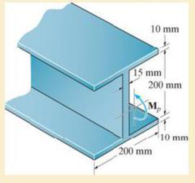
Prob. 6–166
Expert Solution & Answer
Want to see the full answer?
Check out a sample textbook solution
Students have asked these similar questions
||!
Sign in
MMB241 - Tutorial L9.pd X PDF MMB241 - Tutorial L10.pX DE MMB241 - Tutorial L11.p x PDF Lecture W12 - Work and X
File C:/Users/KHULEKANI/Desktop/mmb241/MMB241%20-%20Tutorial%20L11.pdf
PDE Lecture W11 - Power and X
Draw
Alla | Ask Copilot
++
3
of 3
| D
6. If the 50-kg load A is hoisted by motor M so that the load has a constant velocity of 1.5
m/s, determine the power input to the motor, which operates at an efficiency € = 0.8.
1.5 m/s
2
7. The sports car has a mass of 2.3 Mg, and while it is traveling at 28 m/s the driver causes
it to accelerate at 5m/s². If the drag resistance on the car due to the wind is FD= 0.3v²N,
where v is the velocity in m/s, determine the power supplied to the engine at this instant.
The engine has a running efficiency of P = 0.68.
8. If the jet on the dragster supplies a constant thrust of T-20 kN, determine the power
generated by the jet as a function of time. Neglect drag and rolling resistance, and the loss
of fuel. The dragster has a mass of 1…
Q |
Sign in
PDE Lecture W09.pdf
PDF MMB241 - Tutorial L9.pdi X
PDF MMB241 - Tutorial L10.p X
PDF
MMB241 - Tutorial L11.p X
Lecture W12-Work and X
+
File C:/Users/KHULEKANI/Desktop/mmb241/Lecture%20W12%20-%20Work%20and%20Energy.pdf
||!
Draw
| IA | a | Ask Copilot
Class Work
+
33
of 34 D
Question 1
The engine of a 3500-N car is generating a constant power of 50 hp (horsepower)
while the car is traveling up the slope with a constant speed. If the engine is
operating with an efficiency of € 0.8, determine the speed of the car. Neglect
drag and rolling resistance. Use g 9.81 m/s² and 1 hp = 745.7 W.
10
го
Question 2
A man pushes on a 60-N crate with a force F. The force is always directed downward at an angle of 30°
from the horizontal, as shown in the figure. The magnitude of the force is gradually increased until the crate
begins to slide. Determine the crate's initial acceleration once it starts to move. Assume the coefficient of
static friction is μ = 0.6, the coefficient of kinetic…
state is
Derive an expression for the volume expansivity of a substance whose equation of
RT
P
=
v-b
a
v(v + b)TZ
where a and b are empirical constants.
Chapter 6 Solutions
MECHANICS OF MATERIALS (LOOSE)-W/ACCESS
Ch. 6.2 - In each case, the beam is subjected to the...Ch. 6.2 - and then draw the shear and moment diagrams for...Ch. 6.2 - In each case, express the shear and moment...Ch. 6.2 - In each case, express the shear and moment...Ch. 6.2 - In each case, express the shear and moment...Ch. 6.2 - In each case, draw the shear and moment diagrams...Ch. 6.2 - In each case, draw the shear and moment diagrams...Ch. 6.2 - In each case, draw the shear and moment diagrams...Ch. 6.2 - In each case, draw the shear and moment diagrams...Ch. 6.2 - Draw the shear and moment diagrams for the shaft...
Ch. 6.2 - Draw the shear and moment diagrams for the beam,...Ch. 6.2 - Draw the shear and moment diagrams for the beam,...Ch. 6.2 - Express the shear and moment in terms of x for 0 ...Ch. 6.2 - Express the internal shear and moment in the...Ch. 6.2 - Draw the shear and moment diagrams for the shaft....Ch. 6.2 - Express the internal shear and moment in terms of...Ch. 6.2 - Draw the shear and moment diagrams for the beam,...Ch. 6.2 - If the force applied to the handle of the load...Ch. 6.2 - Draw the shear and moment diagrams for the shaft....Ch. 6.2 - The crane is used to support the engine, which has...Ch. 6.2 - Draw the shear and moment diagrams for the beam....Ch. 6.2 - Draw the shear and moment diagrams for the beam....Ch. 6.2 - Draw the shear and moment diagrams for the beam....Ch. 6.2 - Members ABC and BD of the counter chair are...Ch. 6.2 - A reinforced concrete pier is used to support the...Ch. 6.2 - Draw the shear and moment diagrams for the beam...Ch. 6.2 - The industrial robot is held in the stationary...Ch. 6.2 - Determine the placement distance a of the roller...Ch. 6.2 - Draw the shear and moment diagrams for the beam....Ch. 6.2 - Draw the shear and moment diagrams for the beam....Ch. 6.2 - Draw the shear and moment diagrams for the...Ch. 6.2 - The 150-lb man sits in the center of the boat,...Ch. 6.2 - Draw the shear and moment diagrams for the beam....Ch. 6.2 - The footing supports the load transmitted by the...Ch. 6.2 - Draw the shear and moment diagrams for the beam....Ch. 6.2 - Draw the shear and moment diagrams for the beam....Ch. 6.2 - Draw the shear and moment diagrams for the beam....Ch. 6.2 - Draw the shear and moment diagrams for the beam....Ch. 6.2 - Draw the shear and moment diagrams for the beam....Ch. 6.2 - The support at A allows the beam to slide freely...Ch. 6.2 - The smooth pin is supported by two leaves A and B...Ch. 6.2 - The shaft is supported by a smooth thrust bearing...Ch. 6.2 - Draw the shear and moment diagrams for the...Ch. 6.2 - Draw the shear and moment diagrams for the beam....Ch. 6.2 - Draw the shear and moment diagrams for the rod....Ch. 6.2 - Draw the shear and moment diagrams for the beam...Ch. 6.2 - The beam is used to support a uniform load along...Ch. 6.2 - Draw the shear and moment diagrams for the double...Ch. 6.2 - Draw the shear and moment diagrams for the simply...Ch. 6.2 - The compound beam is fixed at A, pin connected at...Ch. 6.2 - Draw the shear and moment diagrams for the...Ch. 6.2 - The compound beam is fixed at A, pin connected at...Ch. 6.2 - Draw the shear and moment diagrams for the beam....Ch. 6.2 - A short link at B is used to connect beams AB and...Ch. 6.2 - The truck is to be used to transport the concrete...Ch. 6.4 - Determine the moment of inertia of the cross...Ch. 6.4 - Determine the location of the centroid, y, and the...Ch. 6.4 - In each case, show how the bending stress acts on...Ch. 6.4 - Sketch the bending stress distribution over each...Ch. 6.4 - If the beam is subjected to a bending moment of M...Ch. 6.4 - If the beam is subjected to a bending moment of M...Ch. 6.4 - If the beam is subjected to a bending moment of M...Ch. 6.4 - If the beam is subjected to a bending moment of M...Ch. 6.4 - If the beam is subjected to a bending moment of M...Ch. 6.4 - An A-36 steel strip has an allowable bending...Ch. 6.4 - Determine the moment M that will produce a maximum...Ch. 6.4 - Determine the maximum tensile and compressive...Ch. 6.4 - The beam is constructed from four pieces of wood,...Ch. 6.4 - The beam is constructed from four pieces of wood,...Ch. 6.4 - The beam is made from three boards nailed together...Ch. 6.4 - The beam is made from three boards nailed together...Ch. 6.4 - If the built-up beam is subjected to an internal...Ch. 6.4 - If the built-up beam is subjected to an internal...Ch. 6.4 - The beam is subjected to a moment of M = 40 kN m....Ch. 6.4 - The steel shaft has a diameter of 2 in. It is...Ch. 6.4 - The beam is made of steel that has an allowable...Ch. 6.4 - A shaft is made of a polymer having an elliptical...Ch. 6.4 - Solve Prob. 6-65 if the moment M = 50 N m is...Ch. 6.4 - Prob. 6.67PCh. 6.4 - The shaft is supported by smooth journal bearings...Ch. 6.4 - The axle of the freight car is subjected to a...Ch. 6.4 - The strut on the utility pole supports the cable...Ch. 6.4 - The boat has a weight of 2300 lb and a center of...Ch. 6.4 - Determine the absolute maximum bending stress in...Ch. 6.4 - Determine the smallest allowable diameter of the...Ch. 6.4 - The pin is used to connect the three links...Ch. 6.4 - The shaft is supported by a thrust bearing at A...Ch. 6.4 - A timber beam has a cross section which is...Ch. 6.4 - If the beam is subjected to an internal moment of...Ch. 6.4 - If the allowable tensile and compressive stress...Ch. 6.4 - If the beam is subjected to an internal moment of...Ch. 6.4 - If the beam is subjected to a moment of M = 100 kN...Ch. 6.4 - If the beam is made of material having an...Ch. 6.4 - The shaft is supported by a smooth thrust bearing...Ch. 6.4 - The shaft is supported by a thrust bearing at A...Ch. 6.4 - If the intensity of the load w = 15 kN/m,...Ch. 6.4 - If the allowable bending stress is allow = 150...Ch. 6.4 - The beam is subjected to the triangular...Ch. 6.4 - The beam has a rectangular cross section with b =...Ch. 6.4 - Prob. 6.88PCh. 6.4 - If the compound beam in Prob. 642 has a square...Ch. 6.4 - If the beam in Prob. 628 has a rectangular cross...Ch. 6.4 - Determine the absolute maximum bending stress in...Ch. 6.4 - Determine, to the nearest millimeter, the smallest...Ch. 6.4 - Determine the absolute maximum bending stress in...Ch. 6.4 - Determine the absolute maximum bending stress in...Ch. 6.4 - Determine the smallest diameter of the shaft to...Ch. 6.4 - A log that is 2 ft in diameter is to be cut into a...Ch. 6.4 - A log that is 2 ft in diameter is to be cut into a...Ch. 6.4 - If the beam in Prob.63 has a rectangular cross...Ch. 6.4 - The simply supported truss is subjected to the...Ch. 6.4 - If d = 450 mm, determine the absolute maximum...Ch. 6.4 - If the allowable bending stress is allow = 6 MPa,...Ch. 6.4 - The beam has a rectangular cross section as shown....Ch. 6.4 - The beam has the rectangular cross section shown....Ch. 6.5 - Determine the bending stress at corners A and B....Ch. 6.5 - Determine the maximum bending stress in the beams...Ch. 6.5 - The member has a square cross section and is...Ch. 6.5 - The member has a square cross section and is...Ch. 6.5 - Consider the general case of a prismatic beam...Ch. 6.5 - Determine the bending stress at point A of the...Ch. 6.5 - Determine the bending stress at point A of the...Ch. 6.5 - The steel shaft is subjected to the two loads. If...Ch. 6.5 - The 65-mm-diameter steel shaft is subjected to the...Ch. 6.5 - For the section, lz = 31.7(10-5) m4, lY =...Ch. 6.5 - For the section, lz, = 31.7(10-5) m4, lY =...Ch. 6.5 - The box beam is subjected to a moment of M = 15...Ch. 6.5 - Determine the maximum magnitude of the bending...Ch. 6.5 - The shaft is subjected to the vertical and...Ch. 6.5 - For the section, Iy' = 31.7(10-6) m4, Iz' =...Ch. 6.5 - For the section, Iy' = 31.7(10-6) m4, Iz' =...Ch. 6.5 - If the applied distributed loading of w = 4 kN/m...Ch. 6.5 - Determine the maximum allowable intensity w of the...Ch. 6.9 - The composite beam is made of steel (A) bonded to...Ch. 6.9 - The composite beam is made of steel (A) bonded to...Ch. 6.9 - Segment A of the composite beam is made from...Ch. 6.9 - Segment A of the composite beam is made from...Ch. 6.9 - The white spruce beam is reinforced with A-992...Ch. 6.9 - The wooden section of the beam is reinforced with...Ch. 6.9 - The wooden section of the beam is reinforced with...Ch. 6.9 - The Douglas Fir beam is reinforced with A-992...Ch. 6.9 - The steel channel is used to reinforce the wood...Ch. 6.9 - A wood beam is reinforced with steel straps at its...Ch. 6.9 - A bimetallic strip is made from pieces of 2014-T6...Ch. 6.9 - Determine the maximum uniform distributed load w0...Ch. 6.9 - The composite beam is made of A-36 steel (A)...Ch. 6.9 - The composite beam is made of A-36 steel (A)...Ch. 6.9 - If the beam is subjected to a moment of M = 45 kN...Ch. 6.9 - The Douglas Fir beam is reinforced with A-36 steel...Ch. 6.9 - For the curved beam in Fig. 640a, show that when...Ch. 6.9 - The curved member is subjected to the moment of M...Ch. 6.9 - The curved member is made from material having an...Ch. 6.9 - The curved beam is subjected to a moment of M = 40...Ch. 6.9 - The curved beam is made from material having an...Ch. 6.9 - If P = 3 kN, determine the bending stress at...Ch. 6.9 - If the maximum bending stress at section a-a is...Ch. 6.9 - The elbow of the pipe has an outer radius of 0.75...Ch. 6.9 - If the bar is subjected to a couple as shown,...Ch. 6.9 - The curved bar used on a machine has a rectangular...Ch. 6.9 - The steel rod has a circular cross section. If it...Ch. 6.9 - If it is subjected to a moment of M = 5 kN m,...Ch. 6.9 - The member has a circular cross section. If the...Ch. 6.9 - The curved bar used on a machine has a rectangular...Ch. 6.9 - The bar is subjected to a moment of M = 100 N, m....Ch. 6.9 - The allowable bending stress for the bar is allow...Ch. 6.9 - The bar has a thickness of 1 in. and the allowable...Ch. 6.9 - The bar has a thickness of 1 in. and is subjected...Ch. 6.9 - The bar has a thickness of 0.5 in. and the...Ch. 6.9 - If the radius of each notch on the plate is r = 10...Ch. 6.9 - The stepped bar has a thickness of 10 mm....Ch. 6.9 - The bar has a thickness of 0.5 in. and is...Ch. 6.10 - Determine the shape factor for the wide-flange...Ch. 6.10 - The wide-flange member is made from an elastic...Ch. 6.10 - The rod has a circular cross section. If it is...Ch. 6.10 - The rod has a circular cross section. If it is...Ch. 6.10 - The beam is made of an elastic perfectly plastic...Ch. 6.10 - Determine the plastic moment Mp that can be...Ch. 6.10 - Determine the shape factor for the beam. Prob....Ch. 6.10 - The beam is made of elastic perfectly plastic...Ch. 6.10 - Determine the shape factor for the beam. Prob....Ch. 6.10 - The beam is made of an elastic perfectly plastic...Ch. 6.10 - Prob. 6.168PCh. 6.10 - Prob. 6.169PCh. 6.10 - Prob. 6.170PCh. 6.10 - The rod has a circular cross section. If it is...Ch. 6.10 - Determine the shape factor of the cross section....Ch. 6.10 - The beam is made of elastic perfectly plastic...Ch. 6.10 - Determine the shape factor for the member having...Ch. 6.10 - Determine the shape factor of the cross section....Ch. 6.10 - The box beam is made of an elastic perfectly...Ch. 6.10 - The beam is made of an elastic perfectly plastic...Ch. 6.10 - The plexiglass bar has a stress-strain curve that...Ch. 6.10 - The stress-strain diagram for a titanium alloy can...Ch. 6.10 - A beam is made from polypropylene plastic and has...Ch. 6.10 - The bar is made of an aluminum alloy having a...Ch. 6.10 - The beam is made of phenolic, a structural...Ch. 6 - Using appropriate measurements and data, explain...Ch. 6 - Determine the shape factor for the wide-flange...Ch. 6 - The compound beam consists of two segments that...Ch. 6 - The composite beam consists of a wood core and two...Ch. 6 - If it resists a moment of M = 125 N m, determine...Ch. 6 - Determine the maximum bending stress in the handle...Ch. 6 - The curved beam is subjected to a bending moment...Ch. 6 - Determine the shear and moment in the beam as...Ch. 6 - A wooden beam has a square cross section as shown...Ch. 6 - Draw the shear and moment diagrams for the shaft...Ch. 6 - The strut has a square cross section a by a and is...
Knowledge Booster


Learn more about
Need a deep-dive on the concept behind this application? Look no further. Learn more about this topic, mechanical-engineering and related others by exploring similar questions and additional content below.Similar questions
- For a gas whose equation of state is P(v-b)=RT, the specified heat difference Cp-Cv is equal to which of the following (show all work): (a) R (b) R-b (c) R+b (d) 0 (e) R(1+v/b)arrow_forwardof state is Derive an expression for the specific heat difference of a substance whose equation RT P = v-b a v(v + b)TZ where a and b are empirical constants.arrow_forwardTemperature may alternatively be defined as T = ди v Prove that this definition reduces the net entropy change of two constant-volume systems filled with simple compressible substances to zero as the two systems approach thermal equilibrium.arrow_forward
- Using the Maxwell relations, determine a relation for equation of state is (P-a/v²) (v−b) = RT. Os for a gas whose av Tarrow_forward(◉ Homework#8arrow_forwardHomework#8arrow_forwardBox A has a mass of 15 kilograms and is attached to the 20 kilogram Box B using the cord and pulley system shown. The coefficient of kinetic friction between the boxes and surface is 0.2 and the moment of inertia of the pulley is 0.5 kg * m^ 2. After 2 seconds, how far do the boxes move? A бро Barrow_forwardBox A has a mass of 15 kilograms and is attached to the 20 kilogram Box B using the cord and pulley system shown. The coefficient of kinetic friction between the boxes and surface is 0.2 and the moment of inertia of the pulley is 0.5 kg * m^2. Both boxes are 0.25 m long and 0.25 m high. The cord is attached to the bottom of Box A and the middle of box B. After 2 seconds, how far do the boxes move? A From бро Barrow_forwardHomework#8arrow_forwardSign in PDF Lecture W09.pdf PDF MMB241 - Tutorial L9.pdf File C:/Users/KHULEKANI/Desktop/mmb241/MMB241%20-%20Tutorial%20L9.pdf II! Draw | I│Alla | Ask Copilot + of 4 D Topic: Kinetics of Particles: - Forces in dynamic system, Free body diagram, newton's laws of motion, and equations of motion. TQ1. The 10-kg block is subjected to the forces shown. In each case, determine its velocity when t=2s if v 0 when t=0 500 N F = (201) N 300 N (b) TQ2. The 10-kg block is subjected to the forces shown. In each case, determine its velocity at s-8 m if v = 3 m/s at s=0. Motion occurs to the right. 40 N F = (2.5 s) N 200 N 30 N (b) TQ3. Determine the initial acceleration of the 10-kg smooth collar. The spring has an unstretched length of 1 m. 1 σ Q ☆ Q 6 ا الى ☑arrow_forwardSign in PDF Lecture W09.pdf PDF MMB241 - Tutorial L9.pdf File C:/Users/KHULEKANI/Desktop/mmb241/MMB241%20-%20Tutorial%20L9.pdf II! Draw | I│Alla | Ask Copilot + 4 of 4 | D TQ9. If motor M exerts a force of F (10t 2 + 100) N determine the velocity of the 25-kg crate when t kinetic friction between the crate and the plane are μs The crate is initially at rest. on the cable, where t is in seconds, 4s. The coefficients of static and 0.3 and μk = 0.25, respectively. M 3 TQ10. The spring has a stiffness k = 200 N/m and is unstretched when the 25-kg block is at A. Determine the acceleration of the block when s = 0.4 m. The contact surface between the block and the plane is smooth. 0.3 m F= 100 N F= 100 N k = 200 N/m σ Q Q ☆ ا الى 6 ☑arrow_forwardmy ID# is 016948724 please solve this problem step by steparrow_forwardarrow_back_iosSEE MORE QUESTIONSarrow_forward_iosRecommended textbooks for you
 Elements Of ElectromagneticsMechanical EngineeringISBN:9780190698614Author:Sadiku, Matthew N. O.Publisher:Oxford University Press
 Mechanics of Materials (10th Edition)Mechanical EngineeringISBN:9780134319650Author:Russell C. HibbelerPublisher:PEARSON
 Thermodynamics: An Engineering ApproachMechanical EngineeringISBN:9781259822674Author:Yunus A. Cengel Dr., Michael A. BolesPublisher:McGraw-Hill Education
 Control Systems EngineeringMechanical EngineeringISBN:9781118170519Author:Norman S. NisePublisher:WILEY
 Mechanics of Materials (MindTap Course List)Mechanical EngineeringISBN:9781337093347Author:Barry J. Goodno, James M. GerePublisher:Cengage Learning
 Engineering Mechanics: StaticsMechanical EngineeringISBN:9781118807330Author:James L. Meriam, L. G. Kraige, J. N. BoltonPublisher:WILEY
Elements Of ElectromagneticsMechanical EngineeringISBN:9780190698614Author:Sadiku, Matthew N. O.Publisher:Oxford University PressMechanics of Materials (10th Edition)Mechanical EngineeringISBN:9780134319650Author:Russell C. HibbelerPublisher:PEARSONThermodynamics: An Engineering ApproachMechanical EngineeringISBN:9781259822674Author:Yunus A. Cengel Dr., Michael A. BolesPublisher:McGraw-Hill EducationControl Systems EngineeringMechanical EngineeringISBN:9781118170519Author:Norman S. NisePublisher:WILEYMechanics of Materials (MindTap Course List)Mechanical EngineeringISBN:9781337093347Author:Barry J. Goodno, James M. GerePublisher:Cengage LearningEngineering Mechanics: StaticsMechanical EngineeringISBN:9781118807330Author:James L. Meriam, L. G. Kraige, J. N. BoltonPublisher:WILEY
Everything About TRANSVERSE SHEAR in 10 Minutes!! - Mechanics of Materials; Author: Less Boring Lectures;https://www.youtube.com/watch?v=4x0E9yvzfCM;License: Standard Youtube License