
VECTOR MECHANICS FOR ENGINEERS W/CON >B
12th Edition
ISBN: 9781260804638
Author: BEER
Publisher: MCG
expand_more
expand_more
format_list_bulleted
Videos
Textbook Question
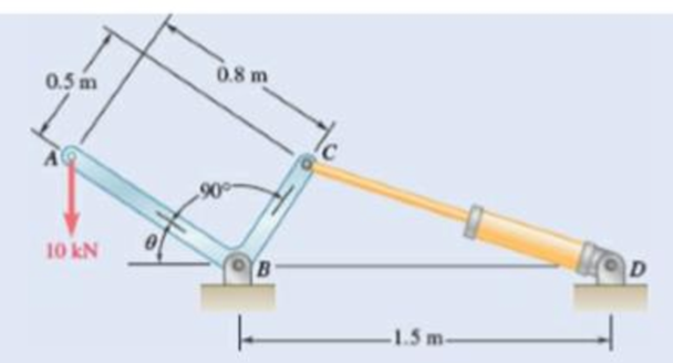
Chapter 6.4, Problem 6.8FBP
The position of member ABC is controlled by the hydraulic cylinder CD. Knowing that θ = 30°, draw the free-body diagram(s) needed to determine the force exerted by the hydraulic cylinder on pin C, and the reaction at B.
Expert Solution & Answer
Want to see the full answer?
Check out a sample textbook solution
Students have asked these similar questions
Please AnswerSteam enters a nozzle at 400°C and 800 kPa with a velocity of 10 m/s and leaves at 375°C and 400 kPa while losing heat at a rate of 26.5 kW. For an inlet area of 800 cm2, determine the velocity and the volume flow rate of the steam at the nozzle exit. Use steam tables.
The velocity of the steam at the nozzle exit is m/s.
The volume flow rate of the steam at the nozzle exit is m3/s.
2. A support hook was formed from a rectangular bar. Find the stresses at the inner and outer
surfaces at sections just above and just below O-B.
-210 mm
120 mm
160 mm
400 N
B
thickness 8 mm
=
Figure 2 - Problem 2
Steam flows steadily through a turbine at a rate of 45,000 lbm/h, entering at 1000 psia and 900°F and leaving at 5 psia as saturated vapor. If the power generated by the turbine is 4.1 MW, determine the rate of heat loss from the steam. The enthalpies are h1 = 1448.6 Btu/lbm and h2 = 1130.7 Btu/lbm.
The rate of heat loss from the steam is Btu/s.
Chapter 6 Solutions
VECTOR MECHANICS FOR ENGINEERS W/CON >B
Ch. 6.1 - Using the method of joints, determine the force in...Ch. 6.1 - Using the method of joints, determine the force in...Ch. 6.1 - Using the method of joints, determine the force in...Ch. 6.1 - Using the method of joints, determine the force in...Ch. 6.1 - Using the method of joints, determine the force in...Ch. 6.1 - Using the method of joints, determine the force in...Ch. 6.1 - Using the method of joints, determine the force in...Ch. 6.1 - Using the method of joints, determine the force in...Ch. 6.1 - Using the method of joints, determine the force in...Ch. 6.1 - Determine the force in each member of the truss...
Ch. 6.1 - Determine the force in each member of the Gambrel...Ch. 6.1 - Determine the force in each member of the Howe...Ch. 6.1 - Using the method of joints, determine the force in...Ch. 6.1 - Using the method of joints, determine the force in...Ch. 6.1 - Determine the force in each member of the Warren...Ch. 6.1 - Solve Problem 6.15 assuming that the load applied...Ch. 6.1 - Determine the force in each member of the Pratt...Ch. 6.1 - The truss shown is one of several supporting an...Ch. 6.1 - Determine the force in each member of the Pratt...Ch. 6.1 - Prob. 6.20PCh. 6.1 - Determine the force in each of the members located...Ch. 6.1 - Determine the force in member DE and in each of...Ch. 6.1 - Determine the force in each of the members located...Ch. 6.1 - The portion of truss shown represents the upper...Ch. 6.1 - For the tower and loading of Prob. 6.24 and...Ch. 6.1 - Solve Problem 6.24 assuming that the cables...Ch. 6.1 - Determine the force in each member of the truss...Ch. 6.1 - Determine the force in each member of the truss...Ch. 6.1 - Determine whether the trusses of Problems 6.31a,...Ch. 6.1 - Determine whether the trusses of Problems 6.31b,...Ch. 6.1 - For the given loading, determine the zero-force...Ch. 6.1 - Prob. 6.32PCh. 6.1 - For the given loading, determine the zero-force...Ch. 6.1 - Prob. 6.34PCh. 6.1 - Prob. 6.35PCh. 6.1 - Prob. 6.36PCh. 6.1 - The truss shown consists of six members and is...Ch. 6.1 - The truss shown consists of nine members and is...Ch. 6.1 - The truss shown consists of nine members and is...Ch. 6.1 - Solve Prob. 6.39 for P = 0 and Q = (900 N)k. 6.39...Ch. 6.1 - The truss shown consists of 18 members and is...Ch. 6.1 - The truss shown consists of 18 members and is...Ch. 6.2 - Determine the force in members BD and DE of the...Ch. 6.2 - Determine the force in members DG and EG of the...Ch. 6.2 - Determine the force in members BD and CD of the...Ch. 6.2 - Determine the force in members DF and DG of the...Ch. 6.2 - A floor truss is loaded as shown. Determine the...Ch. 6.2 - A floor truss is loaded as shown. Determine the...Ch. 6.2 - Determine the force in members CD and DF of the...Ch. 6.2 - Determine the force in members CE and EF of the...Ch. 6.2 - Determine the force in members DE and DF of the...Ch. 6.2 - Prob. 6.52PCh. 6.2 - Determine the force in members DF and DE of the...Ch. 6.2 - Prob. 6.54PCh. 6.2 - A Pratt roof truss is loaded as shown. Determine...Ch. 6.2 - A Pratt roof truss is loaded as shown. Determine...Ch. 6.2 - A Howe scissors roof truss is loaded as shown....Ch. 6.2 - A Howe scissors roof truss is loaded as shown....Ch. 6.2 - Determine the force in members AD, CD, and CE of...Ch. 6.2 - Determine the force in members DG, FG, and FH of...Ch. 6.2 - Determine the force in member GJ of the truss...Ch. 6.2 - Determine the force in members DG and FH of the...Ch. 6.2 - Determine the force in members CD and JK of the...Ch. 6.2 - Determine the force in members DE and KL of the...Ch. 6.2 - The diagonal members in the center panels of the...Ch. 6.2 - The diagonal members in the center panels of the...Ch. 6.2 - Prob. 6.67PCh. 6.2 - Prob. 6.68PCh. 6.2 - Classify each of the structures shown as...Ch. 6.2 - Classify each of the structures shown as...Ch. 6.2 - Prob. 6.71PCh. 6.2 - 6.70 through 6.74 classify as determinate or...Ch. 6.2 - 6.70 through 6.74 classify as determinate or...Ch. 6.2 - 6.70 through 6.74 classify as determinate or...Ch. 6.3 - For the frame and loading shown, draw the...Ch. 6.3 - For the frame and loading shown, draw the...Ch. 6.3 - Draw the free-body diagram(s) needed to determine...Ch. 6.3 - Knowing that the pulley has a radius of 0.5 m,...Ch. 6.3 - and 6.76 Determine the force in member BD and the...Ch. 6.3 - and 6.76 Determine the force in member BD and the...Ch. 6.3 - For the frame and loading shown, determine the...Ch. 6.3 - Determine the components of all forces acting on...Ch. 6.3 - The hydraulic cylinder CF, which partially...Ch. 6.3 - The hydraulic cylinder CF, which partially...Ch. 6.3 - Determine the components of all forces acting on...Ch. 6.3 - Determine the components of all forces acting on...Ch. 6.3 - Determine the components of the reactions at A and...Ch. 6.3 - Determine the components of the reactions at D and...Ch. 6.3 - Determine the components of the reactions at A and...Ch. 6.3 - Determine the components of the reactions at A and...Ch. 6.3 - Prob. 6.87PCh. 6.3 - The 48-lb load can be moved along the line of...Ch. 6.3 - The 48-lb load is removed and a 288-lb in....Ch. 6.3 - (a) Show that, when a frame supports a pulley at...Ch. 6.3 - Knowing that each pulley has a radius of 250 mm,...Ch. 6.3 - Knowing that the pulley has a radius of 75 mm,...Ch. 6.3 - Two 9-in.-diameter pipes (pipe 1 and pipe 2) are...Ch. 6.3 - Prob. 6.94PCh. 6.3 - Prob. 6.95PCh. 6.3 - Prob. 6.96PCh. 6.3 - Prob. 6.97PCh. 6.3 - Prob. 6.98PCh. 6.3 - Knowing that P = 90 lb and Q = 60 lb, determine...Ch. 6.3 - Knowing that P = 90 lb and Q = 60 lb, determine...Ch. 6.3 - For the frame and loading shown, determine the...Ch. 6.3 - For the frame and loading shown, determine the...Ch. 6.3 - Knowing that P = 15 lb and Q = 65 lb, determine...Ch. 6.3 - Knowing that P = 25 lb and Q = 55 lb, determine...Ch. 6.3 - For the frame and loading shown, determine the...Ch. 6.3 - Prob. 6.106PCh. 6.3 - The axis of the three-hinge arch ABC is a parabola...Ch. 6.3 - The axis of the three-hinge arch ABC is a parabola...Ch. 6.3 - Prob. 6.109PCh. 6.3 - Prob. 6.110PCh. 6.3 - 6.111, 6.112, and 6.113 Members ABC and CDE are...Ch. 6.3 - Prob. 6.112PCh. 6.3 - 6.111, 6.112, and 6.113 Members ABC and CDE are...Ch. 6.3 - Members ABC and CDE are pin-connected at C and...Ch. 6.3 - Solve Prob. 6.112 assuming that the force P is...Ch. 6.3 - Solve Prob. 6.114 assuming that the force P is...Ch. 6.3 - Prob. 6.117PCh. 6.3 - Prob. 6.118PCh. 6.3 - 6.119 through 6.121 Each of the frames shown...Ch. 6.3 - 6.119 through 6.121 Each of the frames shown...Ch. 6.3 - 6.119 through 6.121 Each of the frames shown...Ch. 6.4 - An 84-lb force is applied to the toggle vise at C....Ch. 6.4 - For the system and loading shown, draw the...Ch. 6.4 - Prob. 6.7FBPCh. 6.4 - The position of member ABC is controlled by the...Ch. 6.4 - The shear shown is used to cut and trim...Ch. 6.4 - A 100-lb force directed vertically downward is...Ch. 6.4 - Prob. 6.124PCh. 6.4 - The control rod CE passes through a horizontal...Ch. 6.4 - Solve Prob. 6.125 when (a) = 0, (b) = 6. Fig....Ch. 6.4 - The press shown is used to emboss a small seal at...Ch. 6.4 - The press shown is used to emboss a small seal at...Ch. 6.4 - Prob. 6.129PCh. 6.4 - The pin at B is attached to member ABC and can...Ch. 6.4 - Arm ABC is connected by pins to a collar at B and...Ch. 6.4 - Arm ABC is connected by pins to a collar at B and...Ch. 6.4 - The Whitworth mechanism shown is used to produce a...Ch. 6.4 - Prob. 6.134PCh. 6.4 - and 6.136 Two rods are connected by a slider block...Ch. 6.4 - and 6.136 Two rods are connected by a slider block...Ch. 6.4 - 6.137 and 6.138 Rod CD is attached to the collar D...Ch. 6.4 - 6.137 and 6.138 Rod CD is attached to the collar D...Ch. 6.4 - Two hydraulic cylinders control the position of...Ch. 6.4 - Prob. 6.140PCh. 6.4 - A steel ingot weighing 8000 lb is lifted by a pair...Ch. 6.4 - If the toggle shown is added to the tongs of Prob....Ch. 6.4 - A 9-m length of railroad rail of mass 40 kg/m is...Ch. 6.4 - Prob. 6.144PCh. 6.4 - The pliers shown are used to grip a...Ch. 6.4 - Prob. 6.146PCh. 6.4 - In using the bolt cutter shown, a worker applies...Ch. 6.4 - The upper blade and lower handle of the...Ch. 6.4 - Prob. 6.149PCh. 6.4 - and 6.150 Determine the force P that must be...Ch. 6.4 - Prob. 6.151PCh. 6.4 - Prob. 6.152PCh. 6.4 - The elevation of the platform is controlled by two...Ch. 6.4 - For the frame and loading shown, determine the...Ch. 6.4 - The telescoping arm ABC is used to provide an...Ch. 6.4 - The telescoping arm ABC of Prob. 6.155 can be...Ch. 6.4 - The motion of the backhoe bucket shown is...Ch. 6.4 - Prob. 6.158PCh. 6.4 - The gears A and D are rigidly attached to...Ch. 6.4 - In the planetary gear system shown, the radius of...Ch. 6.4 - Two shafts AC and CF, which lie in the vertical xy...Ch. 6.4 - Two shafts AC and CF, which lie in the vertical xy...Ch. 6.4 - The large mechanical tongs shown are used to grab...Ch. 6 - Using the method of joints, determine the force in...Ch. 6 - Using the method of joints, determine the force in...Ch. 6 - A stadium roof truss is loaded as shown. Determine...Ch. 6 - A stadium roof truss is loaded as shown. Determine...Ch. 6 - Determine the components of all forces acting on...Ch. 6 - Prob. 6.169RPCh. 6 - Knowing that the pulley has a radius of 50 mm,...Ch. 6 - For the frame and loading shown, determine the...Ch. 6 - For the frame and loading shown, determine the...Ch. 6 - Water pressure in the supply system exerts a...Ch. 6 - A couple M with a magnitude of 1.5 kNm is applied...Ch. 6 - Prob. 6.175RP
Knowledge Booster


Learn more about
Need a deep-dive on the concept behind this application? Look no further. Learn more about this topic, mechanical-engineering and related others by exploring similar questions and additional content below.Similar questions
- The A/D converter wit the specifications listed below is planned to be used in an environment in which the A/D converter temperature may change by ± 10 °C. Estimate the contributions of conversion and quantization errors to the uncertainty in the digital representation of an analog voltage by the converter. FSO N Linearity error Temperature drift error Analog to Digital (A/D) Converter 0-10 V 12 bits ± 3 bits 1 bit/5 °Carrow_forward6-13. A smooth tube in the form of a circle of radius r rotates in its vertical plane with a constant angular velocity w. The position of a particle of mass m that slides inside the tube is given by the relative coordinate p. Find the differential equation for . e О E g ω Figure P6-13arrow_forwardProblem 2 Consider the power drawn by a resistance load in a DC circuit. The power is calculated as P = VI or P = 1²R. It is given that the normalized uncertainty or % percentage uncertainty in measurements of I, R, and V are the same. Find the uncertainty in P using the two different expressions for power. Is the uncertainty using the two methods the same? If not, WHY, explain?arrow_forward
- A piston–cylinder device contains 3 kg of nitrogen initially at 100 kPa and 25°C. Nitrogen is now compressed slowly in a polytropic process during which PV1.3 = constant until the volume is reduced by one-half. Determine the work done and the heat transfer for this process. The gas constant of N2 is R = 0.2968 kPa·m3/kg·K. The cv value of N2 at the anticipated average temperature of 350 K is 0.744 kJ/kg·K (Table A-2b). The work done for this process is kJ. The heat transfer for this process is kJ.arrow_forwardI tried solving this one but I have no idea where I went wrong can you please help me out with this?arrow_forwardDuring a picnic on a hot summer day, all the cold drinks disappear quickly, and the only available drinks are those at the ambient temperature of 85°F. In an effort to cool a 12- fluid-oz drink in a can, a person grabs the can and starts shaking it in the iced water of the chest at 32°F. Using the properties of water for the drink, determine the mass of ice that will melt by the time the canned drink cools to 37°F. The density and specific heat of water at the average temperature of (85+37)/2 = 61ºF are ρ = 62.3 lbm/ft3 and cp = 1.0 Btu/lbmºF (Table A-3E). The heat of fusion of water is 143.5 Btu/lbm. The mass of ice that will melt by the time the canned drink cools to 37°F is lbm.arrow_forward
- Steam enters a nozzle at 400°C and 800 kPa with a velocity of 10 m/s and leaves at 375°C and 400 kPa while losing heat at a rate of 26.5 kW. For an inlet area of 800 cm2, determine the velocity and the volume flow rate of the steam at the nozzle exit. Use steam tables. At the left side of the lines, 800 kilo Pascal, 400 degree Centigrade, 10 meters per second are shown. At the right side of the lines, 400 kilo Pascal, 375 degree Centigrade are shown. The velocity of the steam at the nozzle exit is m/s. The volume flow rate of the steam at the nozzle exit is m3/s.arrow_forwardA saturated liquid–vapor mixture of water, called wet steam, in a steam line at 1450 kPa is throttled to 50 kPa and 100°C. What is the quality in the steam line? Use data from the steam tables. Above the right side of the tube, 50 kilos 100 degree Centigrade indicated. The quality in the steam line is .arrow_forwardI tried this problems a couple of ways but I don't know what I'm doing wrong can you help me please?arrow_forward
- Refrigerant-134a enters a compressor at 180 kPa as a saturated vapor with a flow rate of 0.35 m3/min and leaves at 900 kPa. The power supplied to the refrigerant during the compression process is 2.35 kW. What is the temperature of R-134a at the exit of the compressor? The temperature of R-134a at the exit of the compressor is °C.arrow_forwardAir enters the compressor of a gas-turbine plant at ambient conditions of 100 kPa and 25°C with a low velocity and exits at 1 MPa and 347°C with a velocity of 90 m/s. The compressor is cooled at a rate of 1500 kJ/min, and the power input to the compressor is 250 kW. Determine the mass flow rate of air through the compressor. The inlet and exit enthalpies of air are 298.2 kJ/kg and 628.07 kJ/kg. The mass flow rate of air is kg/s.arrow_forwardConsider a 1000-W iron whose base plate is made of 0.5-cm-thick aluminum alloy 2024-T6 (ρ = 2770 kg/m3 and cp = 875 J/kg·°C). The base plate has a surface area of 0.03 m2. Initially, the iron is in thermal equilibrium with the ambient air at 22°C. Assuming 90 percent of the heat generated in the resistance wires is transferred to the plate, determine the minimum time needed for the plate temperature to reach 240°C. The minimum time needed for the plate temperature to reach 240°C is s.arrow_forward
arrow_back_ios
SEE MORE QUESTIONS
arrow_forward_ios
Recommended textbooks for you
 International Edition---engineering Mechanics: St...Mechanical EngineeringISBN:9781305501607Author:Andrew Pytel And Jaan KiusalaasPublisher:CENGAGE L
International Edition---engineering Mechanics: St...
Mechanical Engineering
ISBN:9781305501607
Author:Andrew Pytel And Jaan Kiusalaas
Publisher:CENGAGE L
How to balance a see saw using moments example problem; Author: Engineer4Free;https://www.youtube.com/watch?v=d7tX37j-iHU;License: Standard Youtube License