
Videos
6.119 through 6.121 Each of the frames shown consists of two L-shaped members connected by two rigid links. For each frame, determine the reactions at the supports and indicate whether the frame is rigid.
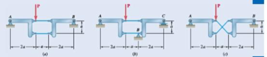
Fig. P6.121
The reactions at the frame and the rigidness of the frame.
Answer to Problem 6.121P
The reactions at the frame for figure (a) is
Explanation of Solution
The following figure gives the free body diagram of the first part of the member in figure P6.121(a).
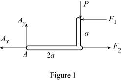
Write the equation to find the moment of force.
Here,
Write the equation to find the total moment about the point
Write the equations for equilibrium for the free body diagram in figure 1.
Here,
The following figure gives the free body diagram of the second part of the member in figure P6.121(a).
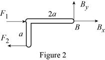
Write the equations for equilibrium for the free body diagram in figure 2.
Here,
The following figure gives the free body diagram of the first part of the member in figure P6.119(b).
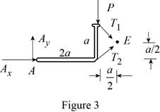
Write the equations for equilibrium for the free body diagram in figure 3.
Here,
The following figure gives the free body diagram of the second part of the member in figure P6.119(b).
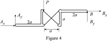
Write the equations for equilibrium for the free body diagram in figure 4.
Here,
The following figure gives the free body diagram of the member in figure P6.119(c).
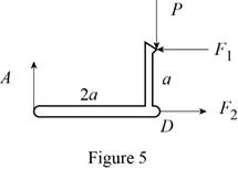
Write the equations for equilibrium for the free body diagram in figure 5.
Here,
The following figure gives the free body diagram of right part of the member in figure P6.119(c).
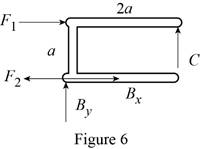
Write the equations for equilibrium for the free body diagram in figure 6.
Here,
Write the expression to find the magnitude of the vector from its components.
Here,
Write the equation to find the angle of orientation of the vector
Conclusion:
Solve equation (I) using figure 1.
Rewrite the above equation.
Solve equation (III) using figure 1.
Rewrite the above equation.
Solve equation (IV) using figure 2.
Rewrite the above equation.
Solve equation (V) using figure 2.
Substitute
Solve equation (VI) using figure 2.
Substitute
Rewrite equation (XIV) in terms of the vector
Substitute
Rewrite equation (XV) in terms of the vector
Substitute
Rewrite equation (XIV) in terms of the vector
Substitute
Solve equation (VII) using figure 3.
Rewrite the above equation.
Solve equation (VIII) using figure 4.
Rewrite the above equation.
Solve the conditions obtained from figure 3 and 4.
Solve equation (IX) using figure 5.
Rewrite the above equation to find
Solve equation (X) using figure 5.
Substitute
Solve equation (XI) using figure 5.
Substitute
Solve equation (XII) using figure 6.
Substitute
Solve equation (XII) to the right using figure 6.
Substitute
Solve equation (XII) upwards using figure 6.
Substitute
Therefore, the reactions at the frame for figure (a) is
Want to see more full solutions like this?
Chapter 6 Solutions
VECTOR MECHANICS FOR ENGINEERS W/CON >B


- Problem 1 Consider R has a functional relationship with variables in the form R = K xq xx using show that n ✓ - (OR 1.) = i=1 2 Их Ux2 Ихэ 2 (177)² = ² (1)² + b² (12)² + c² (1)² 2 UR R x2 x3arrow_forward4. Figure 3 shows a crank loaded by a force F = 1000 N and Mx = 40 Nm. a. Draw a free-body diagram of arm 2 showing the values of all forces, moments, and torques that act due to force F. Label the directions of the coordinate axes on this diagram. b. Draw a free-body diagram of arm 2 showing the values of all forces, moments, and torques that act due to moment Mr. Label the directions of the coordinate axes on this diagram. Draw a free body diagram of the wall plane showing all the forces, torques, and moments acting there. d. Locate a stress element on the top surface of the shaft at A and calculate all the stress components that act upon this element. e. Determine the principal stresses and maximum shear stresses at this point at A.arrow_forward3. Given a heat treated 6061 aluminum, solid, elliptical column with 200 mm length, 200 N concentric load, and a safety factor of 1.2, design a suitable column if its boundary conditions are fixed-free and the ratio of major to minor axis is 2.5:1. (Use AISC recommended values and round the ellipse dimensions so that both axes are whole millimeters in the correct 2.5:1 ratio.)arrow_forward
- 1. A simply supported shaft is shown in Figure 1 with w₁ = 25 N/cm and M = 20 N cm. Use singularity functions to determine the reactions at the supports. Assume El = 1000 kN cm². Wo M 0 10 20 30 40 50 60 70 80 90 100 110 cm Figure 1 - Problem 1arrow_forwardPlease AnswerSteam enters a nozzle at 400°C and 800 kPa with a velocity of 10 m/s and leaves at 375°C and 400 kPa while losing heat at a rate of 26.5 kW. For an inlet area of 800 cm2, determine the velocity and the volume flow rate of the steam at the nozzle exit. Use steam tables. The velocity of the steam at the nozzle exit is m/s. The volume flow rate of the steam at the nozzle exit is m3/s.arrow_forward2. A support hook was formed from a rectangular bar. Find the stresses at the inner and outer surfaces at sections just above and just below O-B. -210 mm 120 mm 160 mm 400 N B thickness 8 mm = Figure 2 - Problem 2arrow_forward
- Steam flows steadily through a turbine at a rate of 45,000 lbm/h, entering at 1000 psia and 900°F and leaving at 5 psia as saturated vapor. If the power generated by the turbine is 4.1 MW, determine the rate of heat loss from the steam. The enthalpies are h1 = 1448.6 Btu/lbm and h2 = 1130.7 Btu/lbm. The rate of heat loss from the steam is Btu/s.arrow_forwardThe A/D converter wit the specifications listed below is planned to be used in an environment in which the A/D converter temperature may change by ± 10 °C. Estimate the contributions of conversion and quantization errors to the uncertainty in the digital representation of an analog voltage by the converter. FSO N Linearity error Temperature drift error Analog to Digital (A/D) Converter 0-10 V 12 bits ± 3 bits 1 bit/5 °Carrow_forward6-13. A smooth tube in the form of a circle of radius r rotates in its vertical plane with a constant angular velocity w. The position of a particle of mass m that slides inside the tube is given by the relative coordinate p. Find the differential equation for . e О E g ω Figure P6-13arrow_forward
- Problem 2 Consider the power drawn by a resistance load in a DC circuit. The power is calculated as P = VI or P = 1²R. It is given that the normalized uncertainty or % percentage uncertainty in measurements of I, R, and V are the same. Find the uncertainty in P using the two different expressions for power. Is the uncertainty using the two methods the same? If not, WHY, explain?arrow_forwardA piston–cylinder device contains 3 kg of nitrogen initially at 100 kPa and 25°C. Nitrogen is now compressed slowly in a polytropic process during which PV1.3 = constant until the volume is reduced by one-half. Determine the work done and the heat transfer for this process. The gas constant of N2 is R = 0.2968 kPa·m3/kg·K. The cv value of N2 at the anticipated average temperature of 350 K is 0.744 kJ/kg·K (Table A-2b). The work done for this process is kJ. The heat transfer for this process is kJ.arrow_forwardI tried solving this one but I have no idea where I went wrong can you please help me out with this?arrow_forward
 Elements Of ElectromagneticsMechanical EngineeringISBN:9780190698614Author:Sadiku, Matthew N. O.Publisher:Oxford University Press
 Mechanics of Materials (10th Edition)Mechanical EngineeringISBN:9780134319650Author:Russell C. HibbelerPublisher:PEARSON
 Thermodynamics: An Engineering ApproachMechanical EngineeringISBN:9781259822674Author:Yunus A. Cengel Dr., Michael A. BolesPublisher:McGraw-Hill Education
 Control Systems EngineeringMechanical EngineeringISBN:9781118170519Author:Norman S. NisePublisher:WILEY
 Mechanics of Materials (MindTap Course List)Mechanical EngineeringISBN:9781337093347Author:Barry J. Goodno, James M. GerePublisher:Cengage Learning
 Engineering Mechanics: StaticsMechanical EngineeringISBN:9781118807330Author:James L. Meriam, L. G. Kraige, J. N. BoltonPublisher:WILEY