
EBK MECHANICS OF MATERIALS
10th Edition
ISBN: 8220102744110
Author: HIBBELER
Publisher: PEARSON
expand_more
expand_more
format_list_bulleted
Videos
Textbook Question
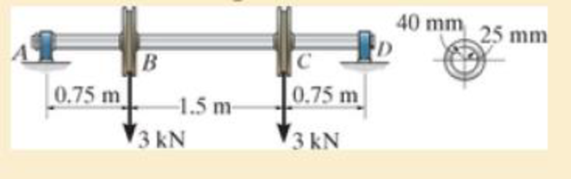
Chapter 6.4, Problem 6.75P
The shaft is supported by a thrust bearing at A and journal bearing at D. If the shaft has the cross section shown, determine the absolute maximum bending stress in the shaft.
Expert Solution & Answer
Want to see the full answer?
Check out a sample textbook solution
Students have asked these similar questions
> Homework 4 - Spring 2025.pdf
Spring 2025.pdf
k 4 - Spring 2025.pdf (447 KB)
Due: Thursday, February 27
Page
1
> of 2
ZOOM
1. A simply supported shaft is shown in Figure 1 with wo = 25 N/cm and M = 20 N cm. Use
singularity functions to determine the reactions at the supports. Assume EI = 1000 kN cm².
M
Wo
0 10 20 30 40 50 60 70
80 90
100 110 cm
Figure 1 - Problem 1
2. A support hook was formed from a rectangular bar. Find the stresses at the inner and outer
surfaces at sections just above and just below O-B.
210 mm
A distillation column with a total condenser and a partial reboiler is separating ethanol andwater at 1.0 atm. Feed is 0.32 mol fraction ethanol and it enters as a saturated liquid at 100mol/s on the optimum plate. The distillate product is a saturated liquid with 80 mol% ethanol.The condenser removes 5615 kW. The bottoms product is 0.05 mol fraction ethanol. AssumeCMO is valid.(a) Find the number of equilibrium stages for this separation. [6 + PR](b) Find how much larger the actual reflux ratio, R, used is than Rmin, i.e. R/Rmin. [3]Note: the heats of vaporization of ethanol and water are λe = 38.58 and λw = 40.645
We have a feed that is a binary mixture of methanol and water (60.0 mol% methanol) that issent to a system of two flash drums hooked together. The vapor from the first drum is cooled,which partially condenses the vapor, and then is fed to the second flash drum. Both drumsoperate at 1.0 atm and are adiabatic. The feed to the first drum is 1000 kmol/hr. We desire aliquid product from the first drum that is 35.0 mol% methanol. The second drum operates at afraction vaporized of (V/F)2 = 0.25.(a) Find the liquid flow rate leaving the first flash drum, L1 (kmol/hr). [286 kmol/hr](b) Find the vapor composition leaving the second flash drum, y2. [0.85]
Chapter 6 Solutions
EBK MECHANICS OF MATERIALS
Ch. 6.2 - In each case, the beam is subjected to the...Ch. 6.2 - and then draw the shear and moment diagrams for...Ch. 6.2 - In each case, express the shear and moment...Ch. 6.2 - In each case, express the shear and moment...Ch. 6.2 - In each case, express the shear and moment...Ch. 6.2 - In each case, draw the shear and moment diagrams...Ch. 6.2 - In each case, draw the shear and moment diagrams...Ch. 6.2 - In each case, draw the shear and moment diagrams...Ch. 6.2 - In each case, draw the shear and moment diagrams...Ch. 6.2 - Draw the shear and moment diagrams for the shaft...
Ch. 6.2 - Draw the shear and moment diagrams for the beam,...Ch. 6.2 - Draw the shear and moment diagrams for the beam,...Ch. 6.2 - Express the shear and moment in terms of x for 0 ...Ch. 6.2 - Express the internal shear and moment in the...Ch. 6.2 - Draw the shear and moment diagrams for the shaft....Ch. 6.2 - Express the internal shear and moment in terms of...Ch. 6.2 - Draw the shear and moment diagrams for the beam,...Ch. 6.2 - If the force applied to the handle of the load...Ch. 6.2 - Draw the shear and moment diagrams for the shaft....Ch. 6.2 - The crane is used to support the engine, which has...Ch. 6.2 - Draw the shear and moment diagrams for the beam....Ch. 6.2 - Draw the shear and moment diagrams for the beam....Ch. 6.2 - Draw the shear and moment diagrams for the beam....Ch. 6.2 - Members ABC and BD of the counter chair are...Ch. 6.2 - A reinforced concrete pier is used to support the...Ch. 6.2 - Draw the shear and moment diagrams for the beam...Ch. 6.2 - The industrial robot is held in the stationary...Ch. 6.2 - Determine the placement distance a of the roller...Ch. 6.2 - Draw the shear and moment diagrams for the beam....Ch. 6.2 - Draw the shear and moment diagrams for the beam....Ch. 6.2 - Draw the shear and moment diagrams for the...Ch. 6.2 - The 150-lb man sits in the center of the boat,...Ch. 6.2 - Draw the shear and moment diagrams for the beam....Ch. 6.2 - The footing supports the load transmitted by the...Ch. 6.2 - Draw the shear and moment diagrams for the beam....Ch. 6.2 - Draw the shear and moment diagrams for the beam....Ch. 6.2 - Draw the shear and moment diagrams for the beam....Ch. 6.2 - Draw the shear and moment diagrams for the beam....Ch. 6.2 - Draw the shear and moment diagrams for the beam....Ch. 6.2 - The support at A allows the beam to slide freely...Ch. 6.2 - The smooth pin is supported by two leaves A and B...Ch. 6.2 - The shaft is supported by a smooth thrust bearing...Ch. 6.2 - Draw the shear and moment diagrams for the...Ch. 6.2 - Draw the shear and moment diagrams for the beam....Ch. 6.2 - Draw the shear and moment diagrams for the rod....Ch. 6.2 - Draw the shear and moment diagrams for the beam...Ch. 6.2 - The beam is used to support a uniform load along...Ch. 6.2 - Draw the shear and moment diagrams for the double...Ch. 6.2 - Draw the shear and moment diagrams for the simply...Ch. 6.2 - The compound beam is fixed at A, pin connected at...Ch. 6.2 - Draw the shear and moment diagrams for the...Ch. 6.2 - The compound beam is fixed at A, pin connected at...Ch. 6.2 - Draw the shear and moment diagrams for the beam....Ch. 6.2 - A short link at B is used to connect beams AB and...Ch. 6.2 - The truck is to be used to transport the concrete...Ch. 6.4 - Determine the moment of inertia of the cross...Ch. 6.4 - Determine the location of the centroid, y, and the...Ch. 6.4 - In each case, show how the bending stress acts on...Ch. 6.4 - Sketch the bending stress distribution over each...Ch. 6.4 - If the beam is subjected to a bending moment of M...Ch. 6.4 - If the beam is subjected to a bending moment of M...Ch. 6.4 - If the beam is subjected to a bending moment of M...Ch. 6.4 - If the beam is subjected to a bending moment of M...Ch. 6.4 - If the beam is subjected to a bending moment of M...Ch. 6.4 - An A-36 steel strip has an allowable bending...Ch. 6.4 - Determine the moment M that will produce a maximum...Ch. 6.4 - Determine the maximum tensile and compressive...Ch. 6.4 - The beam is constructed from four pieces of wood,...Ch. 6.4 - The beam is constructed from four pieces of wood,...Ch. 6.4 - The beam is made from three boards nailed together...Ch. 6.4 - The beam is made from three boards nailed together...Ch. 6.4 - If the built-up beam is subjected to an internal...Ch. 6.4 - If the built-up beam is subjected to an internal...Ch. 6.4 - The beam is subjected to a moment of M = 40 kN m....Ch. 6.4 - The steel shaft has a diameter of 2 in. It is...Ch. 6.4 - The beam is made of steel that has an allowable...Ch. 6.4 - A shaft is made of a polymer having an elliptical...Ch. 6.4 - Solve Prob. 6-65 if the moment M = 50 N m is...Ch. 6.4 - Prob. 6.67PCh. 6.4 - The shaft is supported by smooth journal bearings...Ch. 6.4 - The axle of the freight car is subjected to a...Ch. 6.4 - The strut on the utility pole supports the cable...Ch. 6.4 - The boat has a weight of 2300 lb and a center of...Ch. 6.4 - Determine the absolute maximum bending stress in...Ch. 6.4 - Determine the smallest allowable diameter of the...Ch. 6.4 - The pin is used to connect the three links...Ch. 6.4 - The shaft is supported by a thrust bearing at A...Ch. 6.4 - A timber beam has a cross section which is...Ch. 6.4 - If the beam is subjected to an internal moment of...Ch. 6.4 - If the allowable tensile and compressive stress...Ch. 6.4 - If the beam is subjected to an internal moment of...Ch. 6.4 - If the beam is subjected to a moment of M = 100 kN...Ch. 6.4 - If the beam is made of material having an...Ch. 6.4 - The shaft is supported by a smooth thrust bearing...Ch. 6.4 - The shaft is supported by a thrust bearing at A...Ch. 6.4 - If the intensity of the load w = 15 kN/m,...Ch. 6.4 - If the allowable bending stress is allow = 150...Ch. 6.4 - The beam is subjected to the triangular...Ch. 6.4 - The beam has a rectangular cross section with b =...Ch. 6.4 - Prob. 6.88PCh. 6.4 - If the compound beam in Prob. 642 has a square...Ch. 6.4 - If the beam in Prob. 628 has a rectangular cross...Ch. 6.4 - Determine the absolute maximum bending stress in...Ch. 6.4 - Determine, to the nearest millimeter, the smallest...Ch. 6.4 - Determine the absolute maximum bending stress in...Ch. 6.4 - Determine the absolute maximum bending stress in...Ch. 6.4 - Determine the smallest diameter of the shaft to...Ch. 6.4 - A log that is 2 ft in diameter is to be cut into a...Ch. 6.4 - A log that is 2 ft in diameter is to be cut into a...Ch. 6.4 - If the beam in Prob.63 has a rectangular cross...Ch. 6.4 - The simply supported truss is subjected to the...Ch. 6.4 - If d = 450 mm, determine the absolute maximum...Ch. 6.4 - If the allowable bending stress is allow = 6 MPa,...Ch. 6.4 - The beam has a rectangular cross section as shown....Ch. 6.4 - The beam has the rectangular cross section shown....Ch. 6.5 - Determine the bending stress at corners A and B....Ch. 6.5 - Determine the maximum bending stress in the beams...Ch. 6.5 - The member has a square cross section and is...Ch. 6.5 - The member has a square cross section and is...Ch. 6.5 - Consider the general case of a prismatic beam...Ch. 6.5 - Determine the bending stress at point A of the...Ch. 6.5 - Determine the bending stress at point A of the...Ch. 6.5 - The steel shaft is subjected to the two loads. If...Ch. 6.5 - The 65-mm-diameter steel shaft is subjected to the...Ch. 6.5 - For the section, lz = 31.7(10-5) m4, lY =...Ch. 6.5 - For the section, lz, = 31.7(10-5) m4, lY =...Ch. 6.5 - The box beam is subjected to a moment of M = 15...Ch. 6.5 - Determine the maximum magnitude of the bending...Ch. 6.5 - The shaft is subjected to the vertical and...Ch. 6.5 - For the section, Iy' = 31.7(10-6) m4, Iz' =...Ch. 6.5 - For the section, Iy' = 31.7(10-6) m4, Iz' =...Ch. 6.5 - If the applied distributed loading of w = 4 kN/m...Ch. 6.5 - Determine the maximum allowable intensity w of the...Ch. 6.9 - The composite beam is made of steel (A) bonded to...Ch. 6.9 - The composite beam is made of steel (A) bonded to...Ch. 6.9 - Segment A of the composite beam is made from...Ch. 6.9 - Segment A of the composite beam is made from...Ch. 6.9 - The white spruce beam is reinforced with A-992...Ch. 6.9 - The wooden section of the beam is reinforced with...Ch. 6.9 - The wooden section of the beam is reinforced with...Ch. 6.9 - The Douglas Fir beam is reinforced with A-992...Ch. 6.9 - The steel channel is used to reinforce the wood...Ch. 6.9 - A wood beam is reinforced with steel straps at its...Ch. 6.9 - A bimetallic strip is made from pieces of 2014-T6...Ch. 6.9 - Determine the maximum uniform distributed load w0...Ch. 6.9 - The composite beam is made of A-36 steel (A)...Ch. 6.9 - The composite beam is made of A-36 steel (A)...Ch. 6.9 - If the beam is subjected to a moment of M = 45 kN...Ch. 6.9 - The Douglas Fir beam is reinforced with A-36 steel...Ch. 6.9 - For the curved beam in Fig. 640a, show that when...Ch. 6.9 - The curved member is subjected to the moment of M...Ch. 6.9 - The curved member is made from material having an...Ch. 6.9 - The curved beam is subjected to a moment of M = 40...Ch. 6.9 - The curved beam is made from material having an...Ch. 6.9 - If P = 3 kN, determine the bending stress at...Ch. 6.9 - If the maximum bending stress at section a-a is...Ch. 6.9 - The elbow of the pipe has an outer radius of 0.75...Ch. 6.9 - If the bar is subjected to a couple as shown,...Ch. 6.9 - The curved bar used on a machine has a rectangular...Ch. 6.9 - The steel rod has a circular cross section. If it...Ch. 6.9 - If it is subjected to a moment of M = 5 kN m,...Ch. 6.9 - The member has a circular cross section. If the...Ch. 6.9 - The curved bar used on a machine has a rectangular...Ch. 6.9 - The bar is subjected to a moment of M = 100 N, m....Ch. 6.9 - The allowable bending stress for the bar is allow...Ch. 6.9 - The bar has a thickness of 1 in. and the allowable...Ch. 6.9 - The bar has a thickness of 1 in. and is subjected...Ch. 6.9 - The bar has a thickness of 0.5 in. and the...Ch. 6.9 - If the radius of each notch on the plate is r = 10...Ch. 6.9 - The stepped bar has a thickness of 10 mm....Ch. 6.9 - The bar has a thickness of 0.5 in. and is...Ch. 6.10 - Determine the shape factor for the wide-flange...Ch. 6.10 - The wide-flange member is made from an elastic...Ch. 6.10 - The rod has a circular cross section. If it is...Ch. 6.10 - The rod has a circular cross section. If it is...Ch. 6.10 - The beam is made of an elastic perfectly plastic...Ch. 6.10 - Determine the plastic moment Mp that can be...Ch. 6.10 - Determine the shape factor for the beam. Prob....Ch. 6.10 - The beam is made of elastic perfectly plastic...Ch. 6.10 - Determine the shape factor for the beam. Prob....Ch. 6.10 - The beam is made of an elastic perfectly plastic...Ch. 6.10 - Prob. 6.168PCh. 6.10 - Prob. 6.169PCh. 6.10 - Prob. 6.170PCh. 6.10 - The rod has a circular cross section. If it is...Ch. 6.10 - Determine the shape factor of the cross section....Ch. 6.10 - The beam is made of elastic perfectly plastic...Ch. 6.10 - Determine the shape factor for the member having...Ch. 6.10 - Determine the shape factor of the cross section....Ch. 6.10 - The box beam is made of an elastic perfectly...Ch. 6.10 - The beam is made of an elastic perfectly plastic...Ch. 6.10 - The plexiglass bar has a stress-strain curve that...Ch. 6.10 - The stress-strain diagram for a titanium alloy can...Ch. 6.10 - A beam is made from polypropylene plastic and has...Ch. 6.10 - The bar is made of an aluminum alloy having a...Ch. 6.10 - The beam is made of phenolic, a structural...Ch. 6 - Using appropriate measurements and data, explain...Ch. 6 - Determine the shape factor for the wide-flange...Ch. 6 - The compound beam consists of two segments that...Ch. 6 - The composite beam consists of a wood core and two...Ch. 6 - If it resists a moment of M = 125 N m, determine...Ch. 6 - Determine the maximum bending stress in the handle...Ch. 6 - The curved beam is subjected to a bending moment...Ch. 6 - Determine the shear and moment in the beam as...Ch. 6 - A wooden beam has a square cross section as shown...Ch. 6 - Draw the shear and moment diagrams for the shaft...Ch. 6 - The strut has a square cross section a by a and is...
Knowledge Booster


Learn more about
Need a deep-dive on the concept behind this application? Look no further. Learn more about this topic, mechanical-engineering and related others by exploring similar questions and additional content below.Similar questions
- = The steel curved bar shown has rectangular cross-section with a radial height h = 6 mm and thickness b = 4mm. The radius of the centroidal axis is R = 80 mm. A force P = 10 N is applied as shown. Assume the steel modulus of 207,000 MPa and G = 79.3(103) MPa, repectively. elasticity and shear modulus E = Find the vertical deflection at point B. Use Castigliano's method for a curved flexural member and since R/h > 10, neglect the effect of shear and axial load, thereby assuming that deflection is due to merely the bending moment. Note the inner and outer radii of the curves bar are: r = 80 + ½ (6) = 83 mm, r₁ = 80 − ½ (6) = 77 mm 2 2 Sπ/2 sin² 0 d = √π/² cos² 0 d0 = Π 0 4 大 C R B Parrow_forwardThe steel eyebolt shown in the figure is loaded with a force F = 75 lb. The eyebolt is formed from round wire of diameter d = 0.25 in to a radius R₁ = 0.50 in in the eye and at the shank. Estimate the stresses at the inner and outer surfaces at section A-A. Notice at the section A-A: r₁ = 0.5 in, ro = 0.75 in rc = 0.5 + 0.125 = 0.625 in Ri 200 F FAarrow_forwardI have the fallowing question and solution from a reeds naval arc book. Im just confused as to where this answer came from and the formulas used. Wondering if i could have this answer/ solution broken down and explained in detail. A ship of 7000 tonne displacement has a waterplane areaof 1500 m2. In passing from sea water into river water of1005 kg/m3 there is an increase in draught of 10 cm. Find the Idensity of the sea water. picture of the "answer" is attachedarrow_forward
- Problem A2 long steel tube has a rectangular cross-section with outer dimensions of 20 x 20 mm and a uniform wall thickness of 2. The tube is twisted along its length with torque, T. The tube material is 1045 CD steel with shear yield strength of S,, =315 MPa. Assume shear modulus, G = 79.3GPa. (a) Estimate the maximum torque that can be applied without yielding (b) Estimate the torque required to produce 5 degrees total angle of twist over the length of the tube. (c) What is the maximum torque that can be applied without yielding, if a solid rectangular shaft with dimensions of 20 x 20 is used? You may use the exact solution.arrow_forwardA simply supported beam is loaded as shown. Considering symmetry, the reactions at supports A and B are R₁ = R₂ = wa 2 Using the singularity method, determine the shear force V along the length of the beam as a function of distance x from the support A. A B Ir. 2a За W C R₁₂ x 2. Using the singularity method, determine the bending M along the length of the beam as a function of distance x, from the support A. 3. Using the singularity method, determine the beam slope and deflection along the length of the beam as a function of the distance x, from the support A. Assume the material modulus of elasticity, E and the moment of inertia of the beam cross-section, I are given.arrow_forwardA steel tube, 2 m long, has a rectangular cross-section with outer dimensions of 20 × 30 mm and a uniform wall thickness of 1 mm. The tube is twisted along its length with torque, T. The tube material is 1018 CD steel with shear yield strength of Ssy =185 MPa. Assume shear modulus, G = 79.3GPa. (a) Estimate the maximum torque that can be applied without yielding.- (b) Estimate the torque required to produce 3 degrees total angle of twist over the length of the tube. (c) What is the maximum torque that can be applied without yielding, if a solid rectangular shaft with dimensions of 20 x 30 mm is used? You may use the exact solution:arrow_forward
- |The typical cruising altitude of a commercial jet airliner is 10,700 m above sea level where the local atmospheric temperature is 219 K, and the pressure is 0.25 bar. The aircraft utilizes a cold air-standard Brayton cycle as shown with a volume flow rate of 1450 m³/s. The compressor pressure ratio is 50, and the maximum cycle temperature is 1700 K. The compressor and turbine isentropic efficiencies are 90%. Neglect kinetic and potential energy effects in this problem. Assume constant specific heats with k=1.4, Ra=0.287 kJ/kg- K, Cp=1.0045 kJ/kg-K, and cv = 0.7175 kJ/kg-K. a) Draw a T-s diagram for this cycle on the diagram provided. b) Fill in the table below with the missing information. T[K] Heat exchanger Heat exchanger State P [bar] 1 0.25 2s 2 3 4s 4 Turbine c) (5pts) Determine the inlet air density in [kg/m³] (at state 1), and the system mass flowrate in [kg/s]. d) (10pts) Determine the net power developed in [MW]. Be sure to draw each component you are analyzing, define the…arrow_forwardOn the axis provide, draw a corresponding T-s diagram for the Brayton cycle shown given the following information: iv. V. vi. Compressor 1 is reversible, but Compressor 2 and the turbine are irreversible. The pressure drops through the regenerator are combustors are negligible. The pressures at state (1) and state (10) are equal to the atmospheric pressure. T 8 Regenerator fmm mmm Qin Combustor Compressor Compressor Turbine W cycle Intercooler mm Courarrow_forwardFor parts a) through e), consider the two power cycles shown in the diagram at the right, Cycle A: 1-2-3-4-1, and Cycle B: 1-2-3-4-1. a) What type of power cycles are shown? b) Which of cycles has a higher efficiency? c) Which of the cycles has a higher work output? d) For either cycle, would increasing the maximum cycle temperature (3) increase or decrease the efficiency? Cycle A: 1-2-3-4-1 3 3 Cycle B: 1-2-3-4-1 1 e) For either cycle, would decreasing the minimum cycle temperature (1) increase or decrease the efficiency? f) On the axis provide, draw a corresponding T-s diagram for the Rankine cycle shown given the following information: i. All turbines and pumps in the system are irreversible. ii. 111. The turbine inlet conditions (states 1 and 2) are superheated, while the 2nd stage turbine outlet is a saturated mixture. The condenser outlet state (4) and the CFWH outlet state (7) are saturated liquid. 2 Steam generator Condenser www Closed feedwater heater (1-y) T Pump Trap 8 (y) Sarrow_forward
- Problem 4 A glass sphere with a 30 mm diameter is pressed against a flat carbon steel plate with a force of 5 N. Assume. For glass: E = 46.2 GPa, -0.245 and for steel E, 207 GPa, (a) Determine the radius of the contact surface. -0.292 (4 (b) Determine the maximum pressure at the contact surface. (4 (c) Calculate the principal stresses d., and a, in the glass sphere at the depth=0.037 mm. (d) Maximum shear stress in the glass sphere at the depth: 0.037 mm. (t (4 (e) Draw the Mohr circles for the stresses and show the point corresponding to the maximum shear stress. (3arrow_forwardSteam is the working fluid in the vapor power cycle with reheat shown in the figure. The mass flow rate is 0.5 kg/s, and the turbines and pump operate isentropically. The temperature at the inlet of both turbine stages (i.e. states 1 and 3) is 400 °C The condenser outlet is saturated liquid. 1. Fill in the table below with the missing information. Reheat section High- pressure turbine State P [bar] h [kJ/kg] s [kJ/kg-K] x [-] Steam generator 1 140 Condenser Pump 2 40 5 3 4 4 5 6 2.Draw a T-s diagram for this cycle on the diagram provided 3. Determine the net power output of this cycle in [kW]. Be sure to draw the component(s) you are analyzing, define the system, and apply conservation of energy in the space below. 4.Determine the total heat transferred into the system in [kW]. Be sure to draw the component you are analyzing, define the system, and apply conservation of energy in the space bel 5.Determine the cycle efficiency. Low-pressure turbinearrow_forwardCalculate the moment of F about axis AB. Express the moment as a Cartesian vector, and then state its magnitude. The radii of the curved sections are all 0.5 m. F acts on the bottom center of the hook, and the hook lies in the yz plane.arrow_forward
arrow_back_ios
SEE MORE QUESTIONS
arrow_forward_ios
Recommended textbooks for you
 Elements Of ElectromagneticsMechanical EngineeringISBN:9780190698614Author:Sadiku, Matthew N. O.Publisher:Oxford University Press
 Mechanics of Materials (10th Edition)Mechanical EngineeringISBN:9780134319650Author:Russell C. HibbelerPublisher:PEARSON
 Thermodynamics: An Engineering ApproachMechanical EngineeringISBN:9781259822674Author:Yunus A. Cengel Dr., Michael A. BolesPublisher:McGraw-Hill Education
 Control Systems EngineeringMechanical EngineeringISBN:9781118170519Author:Norman S. NisePublisher:WILEY
 Mechanics of Materials (MindTap Course List)Mechanical EngineeringISBN:9781337093347Author:Barry J. Goodno, James M. GerePublisher:Cengage Learning
 Engineering Mechanics: StaticsMechanical EngineeringISBN:9781118807330Author:James L. Meriam, L. G. Kraige, J. N. BoltonPublisher:WILEY
Elements Of Electromagnetics
Mechanical Engineering
ISBN:9780190698614
Author:Sadiku, Matthew N. O.
Publisher:Oxford University Press
Mechanics of Materials (10th Edition)
Mechanical Engineering
ISBN:9780134319650
Author:Russell C. Hibbeler
Publisher:PEARSON
Thermodynamics: An Engineering Approach
Mechanical Engineering
ISBN:9781259822674
Author:Yunus A. Cengel Dr., Michael A. Boles
Publisher:McGraw-Hill Education
Control Systems Engineering
Mechanical Engineering
ISBN:9781118170519
Author:Norman S. Nise
Publisher:WILEY
Mechanics of Materials (MindTap Course List)
Mechanical Engineering
ISBN:9781337093347
Author:Barry J. Goodno, James M. Gere
Publisher:Cengage Learning
Engineering Mechanics: Statics
Mechanical Engineering
ISBN:9781118807330
Author:James L. Meriam, L. G. Kraige, J. N. Bolton
Publisher:WILEY
BEARINGS BASICS and Bearing Life for Mechanical Design in 10 Minutes!; Author: Less Boring Lectures;https://www.youtube.com/watch?v=aU4CVZo3wgk;License: Standard Youtube License