
Engineering Mechanics: Statics
13th Edition
ISBN: 9780132915540
Author: Russell C. Hibbeler
Publisher: Prentice Hall
expand_more
expand_more
format_list_bulleted
Videos
Textbook Question
Chapter 6.3, Problem 7P
Determine the force in each member of the Pratt truss, and state if the members are in tension or compression.
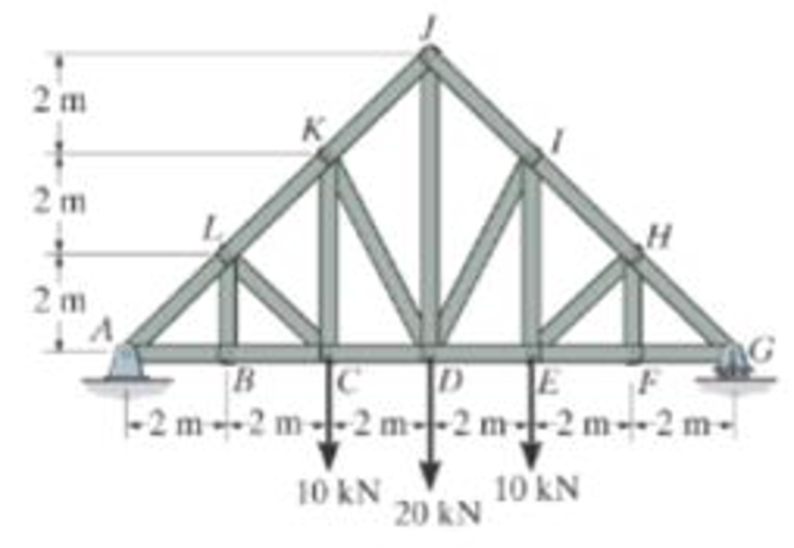
Prob. 6-11
Expert Solution & Answer

Trending nowThis is a popular solution!

Learn your wayIncludes step-by-step video

schedule22:45
Students have asked these similar questions
PROBLEM 3.23
3.23 Under normal operating condi-
tions a motor exerts a torque of
magnitude TF at F. The shafts
are made of a steel for which
the allowable shearing stress is
82 MPa and have diameters of
dCDE=24 mm and dFGH = 20
mm. Knowing that rp = 165
mm and rg114 mm, deter-
mine the largest torque TF
which may be exerted at F.
TF
F
rG-
rp
B
CH
TE
E
1. (16%) (a) If a ductile material fails under pure torsion, please explain the failure
mode and describe the observed plane of failure.
(b) Suppose a prismatic beam is subjected to equal and opposite couples as shown
in Fig. 1. Please sketch the deformation and the stress distribution of the cross
section.
M
M
Fig. 1
(c) Describe the definition of the neutral axis.
(d) Describe the definition of the modular ratio.
using the theorem of three moments, find all the moments, I only need concise calculations with minimal explanations. The correct answers are provided at the bottom
Chapter 6 Solutions
Engineering Mechanics: Statics
Ch. 6.3 - State if the members are in tension or...Ch. 6.3 - State if the members are in tension or...Ch. 6.3 - Prob. 3FPCh. 6.3 - Determine the greatest load P that can be applied...Ch. 6.3 - Identify the zero-force members in the truss....Ch. 6.3 - State if the members are in tension or...Ch. 6.3 - Prob. 1PCh. 6.3 - Prob. 2PCh. 6.3 - Determine the force in each member of the truss,...Ch. 6.3 - Determine the force in each member of the truss,...
Ch. 6.3 - Prob. 5PCh. 6.3 - Determine the force in each member of the truss...Ch. 6.3 - Determine the force in each member of the Pratt...Ch. 6.3 - Prob. 8PCh. 6.3 - Prob. 9PCh. 6.3 - Prob. 10PCh. 6.3 - Determine the force in each member of the truss...Ch. 6.3 - Prob. 12PCh. 6.3 - Prob. 13PCh. 6.3 - Prob. 14PCh. 6.3 - Prob. 15PCh. 6.3 - State whether the members are in tension or...Ch. 6.3 - If the maximum force that any member can support...Ch. 6.3 - Prob. 18PCh. 6.3 - Prob. 19PCh. 6.3 - Prob. 20PCh. 6.3 - Prob. 21PCh. 6.3 - Determine the force in each member of the double...Ch. 6.3 - Prob. 23PCh. 6.3 - Prob. 24PCh. 6.3 - Prob. 25PCh. 6.3 - Prob. 26PCh. 6.4 - Determine the force in members BC, CF, and FE....Ch. 6.4 - State if the members are in tension or...Ch. 6.4 - State if the members are in tension or...Ch. 6.4 - State if the members are in tension or...Ch. 6.4 - State if the members are in tension or...Ch. 6.4 - State if the members are in tension or...Ch. 6.4 - Determine the force in members HG, HE and DE of...Ch. 6.4 - Prob. 28PCh. 6.4 - Prob. 29PCh. 6.4 - Prob. 30PCh. 6.4 - State if these members are in tension or...Ch. 6.4 - State if these members are in tension or...Ch. 6.4 - Prob. 33PCh. 6.4 - Prob. 34PCh. 6.4 - State if these members are in tension or...Ch. 6.4 - Determine the force in members CD, CF, and CG and...Ch. 6.4 - Determine the force in members GF, FB, and BC of...Ch. 6.4 - Prob. 38PCh. 6.4 - Prob. 39PCh. 6.4 - Prob. 40PCh. 6.4 - Prob. 41PCh. 6.4 - Prob. 42PCh. 6.4 - Prob. 43PCh. 6.4 - Prob. 44PCh. 6.4 - Prob. 45PCh. 6.4 - Prob. 46PCh. 6.4 - Prob. 47PCh. 6.4 - Prob. 48PCh. 6.4 - Prob. 49PCh. 6.6 - Determine the force P needed to hold the 60-lb...Ch. 6.6 - Determine the horizontal and vertical components...Ch. 6.6 - If a 100-N force is applied to the handles of the...Ch. 6.6 - Prob. 16FPCh. 6.6 - Determine the normal force that the 100-lb plate A...Ch. 6.6 - Also, determine the proper placement x of the hook...Ch. 6.6 - Determine the components of reaction at A and B....Ch. 6.6 - Determine the reactions at D. Prob. F6-20Ch. 6.6 - Determine the components of reaction at A and C....Ch. 6.6 - Determine the components of reaction at C. Prob....Ch. 6.6 - Determine the components of reaction at E. Prob....Ch. 6.6 - Determine the components of reaction at D and the...Ch. 6.6 - The block weighs 100 lb. Prob. 6-62Ch. 6.6 - Prob. 62PCh. 6.6 - Prob. 63PCh. 6.6 - Prob. 64PCh. 6.6 - Prob. 65PCh. 6.6 - Prob. 66PCh. 6.6 - Prob. 67PCh. 6.6 - Prob. 68PCh. 6.6 - Also, what are the horizontal and vertical...Ch. 6.6 - Prob. 70PCh. 6.6 - Prob. 71PCh. 6.6 - Prob. 72PCh. 6.6 - Prob. 73PCh. 6.6 - Determine the horizontal and vertical components...Ch. 6.6 - Determine the horizontal and vertical components...Ch. 6.6 - Prob. 76PCh. 6.6 - Prob. 77PCh. 6.6 - Prob. 78PCh. 6.6 - The toggle clamp is subjected to a force F at the...Ch. 6.6 - Determine the force P exerted on each of the...Ch. 6.6 - Prob. 81PCh. 6.6 - Determine the force in the guy cable AI and the...Ch. 6.6 - Prob. 83PCh. 6.6 - Prob. 84PCh. 6.6 - Prob. 85PCh. 6.6 - If the wheel at A exerts a normal force of FA = 80...Ch. 6.6 - Prob. 87PCh. 6.6 - Prob. 88PCh. 6.6 - Prob. 89PCh. 6.6 - Determine the force that the jaws J of the metal...Ch. 6.6 - When the walking beam ABC is horizontal, the force...Ch. 6.6 - Prob. 92PCh. 6.6 - Prob. 93PCh. 6.6 - Determine the total force he must exert on bar AB...Ch. 6.6 - Determine the total force he must exert on bar AB...Ch. 6.6 - Prob. 96PCh. 6.6 - Prob. 97PCh. 6.6 - Determine the horizontal and vertical components...Ch. 6.6 - If a clamping force of 300 N is required at A,...Ch. 6.6 - If a force of F = 350 N is applied to the handle...Ch. 6.6 - Prob. 101PCh. 6.6 - Prob. 102PCh. 6.6 - Prob. 103PCh. 6.6 - Prob. 104PCh. 6.6 - Prob. 105PCh. 6.6 - If d = 0.75 ft and the spring has an unstretched...Ch. 6.6 - If a force of F = 50 lb is applied to the pads at...Ch. 6.6 - Determine the force in the hydraulic cylinder AB...Ch. 6.6 - Prob. 109PCh. 6.6 - Prob. 110PCh. 6.6 - Prob. 111PCh. 6.6 - If the sprig has a stiffness of k = 15 lb/in., and...Ch. 6.6 - Prob. 113PCh. 6.6 - Prob. 114PCh. 6.6 - If only vertical forces are supported at the...Ch. 6.6 - Determine the resultant forces at pins B and C on...Ch. 6.6 - Determine the force in each member of the truss...Ch. 6.6 - Determine the horizontal and vertical components...Ch. 6.6 - Prob. 123RPCh. 6.6 - Prob. 124RPCh. 6.6 - Prob. 125RPCh. 6.6 - Determine the force in each member of the truss...
Additional Engineering Textbook Solutions
Find more solutions based on key concepts
Number of Days Worked Design a class called NumDays. The classs purpose is to store a value that represents a n...
Starting Out with C++: Early Objects (9th Edition)
Write a for loop that displays the following set of numbers: 0, 10, 20, 30, 40, 50 . . . 1000
Starting Out with Python (4th Edition)
CONCEPT QUESTIONS
15.CQ3 The ball rolls without slipping on the fixed surface as shown. What is the direction ...
Vector Mechanics for Engineers: Statics and Dynamics
(Displaying a Square of Asterisks) Write a method squareOfAsterisks that displays a solid square (the same numb...
Java How to Program, Early Objects (11th Edition) (Deitel: How to Program)
2-1 List the five types of measurements that form the
basis of traditional ptane surveying-
Elementary Surveying: An Introduction To Geomatics (15th Edition)
Describe two properties that each candidate key must satisfy.
Modern Database Management
Knowledge Booster


Learn more about
Need a deep-dive on the concept behind this application? Look no further. Learn more about this topic, mechanical-engineering and related others by exploring similar questions and additional content below.Similar questions
- PROBLEM 3.46 The solid cylindrical rod BC of length L = 600 mm is attached to the rigid lever AB of length a = 380 mm and to the support at C. When a 500 N force P is applied at A, design specifications require that the displacement of A not exceed 25 mm when a 500 N force P is applied at A For the material indicated determine the required diameter of the rod. Aluminium: Tall = 65 MPa, G = 27 GPa. Aarrow_forwardFind the equivalent mass of the rocker arm assembly with respect to the x coordinate. k₁ mi m2 k₁arrow_forward2. Figure below shows a U-tube manometer open at both ends and containing a column of liquid mercury of length l and specific weight y. Considering a small displacement x of the manometer meniscus from its equilibrium position (or datum), determine the equivalent spring constant associated with the restoring force. Datum Area, Aarrow_forward
- 1. The consequences of a head-on collision of two automobiles can be studied by considering the impact of the automobile on a barrier, as shown in figure below. Construct a mathematical model (i.e., draw the diagram) by considering the masses of the automobile body, engine, transmission, and suspension and the elasticity of the bumpers, radiator, sheet metal body, driveline, and engine mounts.arrow_forward3.) 15.40 – Collar B moves up at constant velocity vB = 1.5 m/s. Rod AB has length = 1.2 m. The incline is at angle = 25°. Compute an expression for the angular velocity of rod AB, ė and the velocity of end A of the rod (✓✓) as a function of v₂,1,0,0. Then compute numerical answers for ȧ & y_ with 0 = 50°.arrow_forward2.) 15.12 The assembly shown consists of the straight rod ABC which passes through and is welded to the grectangular plate DEFH. The assembly rotates about the axis AC with a constant angular velocity of 9 rad/s. Knowing that the motion when viewed from C is counterclockwise, determine the velocity and acceleration of corner F.arrow_forward
arrow_back_ios
SEE MORE QUESTIONS
arrow_forward_ios
Recommended textbooks for you
 Elements Of ElectromagneticsMechanical EngineeringISBN:9780190698614Author:Sadiku, Matthew N. O.Publisher:Oxford University Press
 Mechanics of Materials (10th Edition)Mechanical EngineeringISBN:9780134319650Author:Russell C. HibbelerPublisher:PEARSON
 Thermodynamics: An Engineering ApproachMechanical EngineeringISBN:9781259822674Author:Yunus A. Cengel Dr., Michael A. BolesPublisher:McGraw-Hill Education
 Control Systems EngineeringMechanical EngineeringISBN:9781118170519Author:Norman S. NisePublisher:WILEY
 Mechanics of Materials (MindTap Course List)Mechanical EngineeringISBN:9781337093347Author:Barry J. Goodno, James M. GerePublisher:Cengage Learning
 Engineering Mechanics: StaticsMechanical EngineeringISBN:9781118807330Author:James L. Meriam, L. G. Kraige, J. N. BoltonPublisher:WILEY
Elements Of Electromagnetics
Mechanical Engineering
ISBN:9780190698614
Author:Sadiku, Matthew N. O.
Publisher:Oxford University Press
Mechanics of Materials (10th Edition)
Mechanical Engineering
ISBN:9780134319650
Author:Russell C. Hibbeler
Publisher:PEARSON
Thermodynamics: An Engineering Approach
Mechanical Engineering
ISBN:9781259822674
Author:Yunus A. Cengel Dr., Michael A. Boles
Publisher:McGraw-Hill Education
Control Systems Engineering
Mechanical Engineering
ISBN:9781118170519
Author:Norman S. Nise
Publisher:WILEY
Mechanics of Materials (MindTap Course List)
Mechanical Engineering
ISBN:9781337093347
Author:Barry J. Goodno, James M. Gere
Publisher:Cengage Learning
Engineering Mechanics: Statics
Mechanical Engineering
ISBN:9781118807330
Author:James L. Meriam, L. G. Kraige, J. N. Bolton
Publisher:WILEY
How to balance a see saw using moments example problem; Author: Engineer4Free;https://www.youtube.com/watch?v=d7tX37j-iHU;License: Standard Youtube License